
A progressive flexible flanging device and process for a large-diameter thick-walled cylinder

A thick-walled cylinder and large-diameter technology, which is applied in the field of progressive flexible flanging devices for large-diameter thick-walled cylinders, can solve the problem that the large-diameter thick-walled cylinder cannot meet the forming force and flanging requirements of the large-diameter thick-walled cylinder, and the large-diameter thick-walled cylinder cannot be completed. The problems of the progressive flanging process of the body and the deformation of the roundness of the branch parts can save design time, improve the structure size, and have high forming force.

Active Publication Date: 2019-04-16
XI AN JIAOTONG UNIV
View PDF5 Cites 0 Cited by
  • Summary
  • Abstract
  • Description
  • Claims
  • Application Information

AI Technical Summary

Problems solved by technology

However, there are still many problems in the progressive flanging process in the experiment, such as uneven edge of the branch pipe, deformation of the roundness of the branch part, bending or wrinkling in the transition area between the main pipe and the branch pipe, etc.
However, the above-mentioned progressive flanging process is not suitable for large-diameter thick-walled cylindrical parts. The structure of the tool head and the upward movement of the tool head mentioned in the article cannot meet the forming force and flanging of large-diameter thick-walled cylindrical parts. Require
At the same time, due to the influence of factors such as the size of large-diameter thick-walled cylindrical parts, supporting molds, fixtures, and operating space, the progressive flanging process of large-diameter thick-walled cylindrical parts cannot be completed on ordinary CNC machine tools

Method used


Image

  • A progressive flexible flanging device and process for a large-diameter thick-walled cylinder
  • A progressive flexible flanging device and process for a large-diameter thick-walled cylinder
  • A progressive flexible flanging device and process for a large-diameter thick-walled cylinder

Examples


Embodiment Construction

[0033] The present invention will be described in detail below in conjunction with the accompanying drawings.

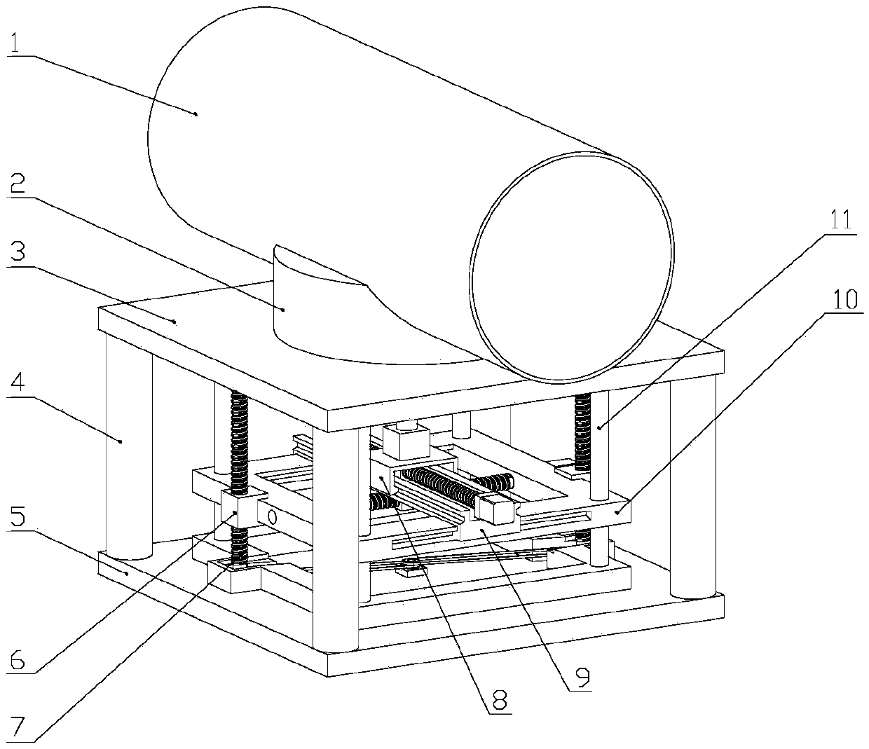
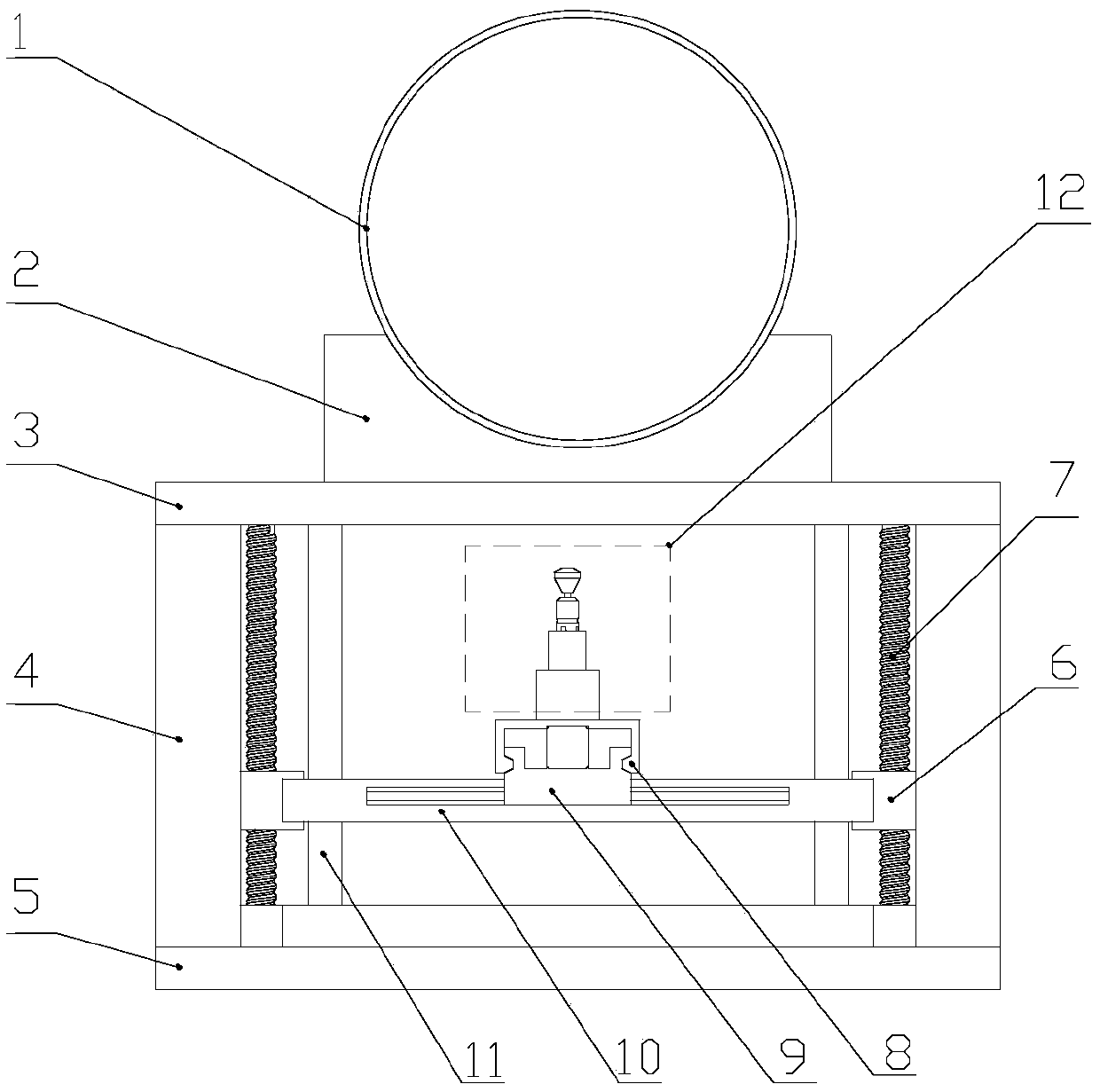
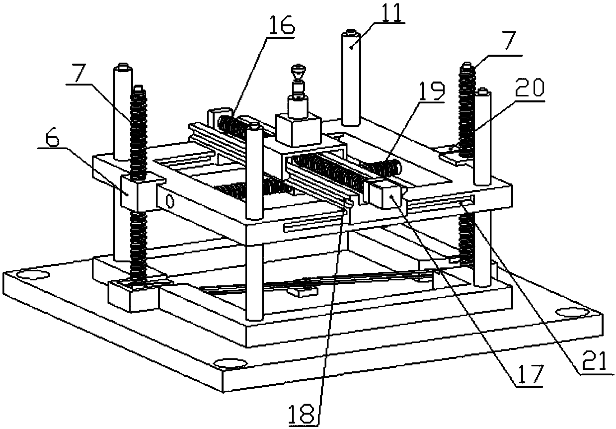
[0034] refer to figure 1 , figure 2 , image 3 , Figure 4 , a progressively flexible flanging device for a large-diameter thick-walled cylinder, including an overall frame, a mobile working platform, and a forming tool system;

[0035] The overall frame includes a lower base 5, the lower base 5 is connected to the upper base 3 through four columns 4, the upper base 3 is equipped with a supporting die 2, and a large-diameter thick-walled cylinder 1 is placed on the supporting die 2;

[0036] A mobile working platform is installed inside the overall frame, and the mobile working platform is located between the upper base 3 and the lower base 5. The mobile working platform includes a Z-axis mobile platform 10 connected to four guide columns 11, and the two ends of the four guide columns 11 Fixed on the lower base 5 and the upper base 3, the Z-axis mobile platform ...


PUM


Abstract

The invention discloses a large-caliber thick-wall cylinder gradual flexible flanging device and process. The device comprises an overall frame connected by a lower base, stand columns and an upper base; a large-caliber thick-wall cylinder is placed on a support concave mold mounted on the upper base; a movable working platform is mounted in the overall frame; the movable working platform comprises a Z-axle movable platform, a Y-axle movable platform connected to the Z-axle movable platform, and an X-axle movable platform connected with the Y-axle movable platform, and realizes movement in space; a forming cutter system is mounted on the X-axle movable platform, and comprises a forming tool head; and the forming tool head is connected with a driving mechanism through a shank. The process comprises the following steps: firstly, the large-caliber thick-wall cylinder is put on the support concave mold, and is opened to the lower side; then, the whole movable working platform is driven forpreforming through a bending deformation area of the forming tool head; and finally, the flanging formation is finished through a flanging forming area of the forming tool head. The device has the characteristics of good forming performances, high yield and the like.

Description

technical field [0001] The invention relates to the technical field of sheet metal forming, in particular to a progressive flexible flanging device and process for a large-diameter thick-walled cylinder. Background technique [0002] Gas-insulated metal-enclosed switchgear (GIS) plays an extremely important role in current domestic and foreign power systems. The GIS shell uses sulfur hexafluoride as the insulating and arc-extinguishing medium, and its high-voltage live parts are enclosed in a metal shell, and its side walls must have branch pipe flanges for the required pipeline connection. For the GIS shell, its tightness requirements are very high, and the welding seam should be avoided as much as possible in the process of manufacturing the shell. If a saddle-shaped opening is used for welding flanges, sharp corners and burrs on the weld seam will be formed, causing electric field Concentration, partial discharge occurs, which reduces the performance of the switch. [0...

Claims


Application Information

Patent Timeline
Patent Type & Authority Patents(China)
IPC IPC(8): B21D19/00
CPCB21D19/00
Inventor 张大伟施天琳赵升吨
Owner XI AN JIAOTONG UNIV
Learn More