Disassembly-prevention fastener

A fastener and anti-disassembly technology, applied in the direction of threaded fasteners, locking fasteners, connecting components, etc., can solve problems such as increasing the difficulty of disassembly

Inactive Publication Date: 2016-12-07
苗超
View PDF7 Cites 3 Cited by
  • Summary
  • Abstract
  • Description
  • Claims
  • Application Information

AI Technical Summary

Problems solved by technology

[0002] Fasteners are an indispensable necessity in our life. They are used to flexibly fix two objects. The fasteners currently used are all detachable. The bolts and nuts can be disassembled freely, but some

Method used


Image

  • Disassembly-prevention fastener
  • Disassembly-prevention fastener
  • Disassembly-prevention fastener

Examples


Embodiment 1

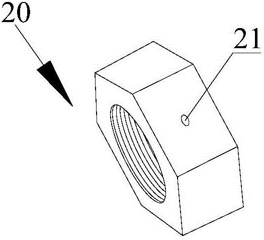
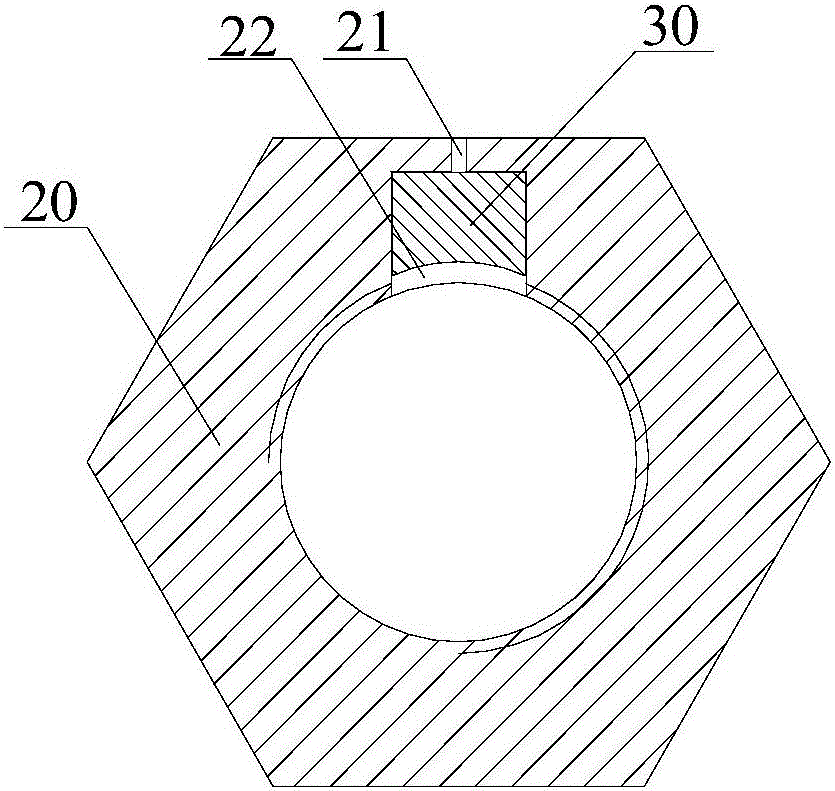
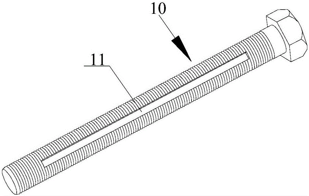
[0016] Anti-tamper fasteners such as figure 1 — image 3 As shown, it includes a bolt 10 and a nut 20. The bolt 10 has a groove 11 along its length, and the nut 20 has a cavity 22 for accommodating the locking block 30. The width of the cavity 22 is the same as the width of the groove 11. Similarly, the bottom of the cavity 22 communicates with the threaded hole of the nut 20, and a through hole 21 runs through the top of the cavity 22 and the outer wall of the nut 20. A locking block 30 is arranged in the cavity 22, and the locking block 30 is connected to the inner wall of the cavity 22. In a transitional fit, the vertical height of the locking block 30 is smaller than the depth of the concave cavity 22 and larger than the depth of the groove 11 .

[0017] When in use, make the groove 11 of the bolt 10 and the concave cavity 22 of the nut 20 position opposite, insert in the through hole 21 with a round stick, and the bottom end of the round stick is against the locking bloc...

Embodiment 2

[0019] Anti-tamper fasteners such as figure 1 , Figure 4 and Figure 5 As shown, it includes a bolt 10 and a nut 20, and the material of the bolt 10 and the nut 20 is iron. The bolt 10 has four grooves 11 along its length, and the nut 20 has a cavity for accommodating the locking block 30. 22. The width of the cavity 22 is the same as the width of the groove 11. The bottom of the cavity 22 communicates with the threaded hole of the nut 20. There is a through hole 21 running through the top of the cavity 22 and the outer wall of the nut 20. The cavity 22 is provided with a lock Block 30, the material of the locking block 30 is a magnet, the locking block 30 is adsorbed in the concave cavity 22, the vertical height of the locking block 30 is less than the depth of the concave cavity 22 and greater than the depth of the groove 11, the locking block 30 There is also a threaded hole 31 on the surface, the threaded hole 31 corresponds to the position of the through hole 21 , and ...


PUM


Abstract

The invention relates to a disassembly-prevention fastener. The disassembly-prevention fastener comprises a bolt and a nut, wherein at least one groove along the length direction is formed in the bolt; a concave cavity used for accommodating a locking block is formed in the nut; the width of the concave cavity is the same as the width of the groove; the bottom of the concave cavity communicates with the threaded hole of the nut; a through hole penetrates through the top of the concave cavity and the outer wall of the nut; the locking block is arranged in the concave cavity; the vertical height of the locking block is smaller than the depth of the concave cavity and is larger than the depth of the groove; during use, the concave cavity in the nut corresponds to the groove in the bolt; then a round rod is inserted into the through hole; the bottom of the round rod is pressed against the locking block; the locking block is pushed hard, so that the bottom of the locking block is in contact with the bottom of the groove; the height of the locking block is larger than the depth of the groove, so that the upper part of the locking block is still located in the concave cavity; and therefore, relative rotation of the bolt and the nut is limited, and the aim of disassembly-prevention is realized.

Description

technical field [0001] The invention relates to a fastener, in particular to an anti-disassembly fastener. Background technique [0002] Fasteners are an indispensable necessity in our life. They are used to flexibly fix two objects. The fasteners currently used are all detachable. The bolts and nuts can be disassembled freely, but some special places need to install the nuts. Finally, it is permanently fixed on the bolt or greatly increases the difficulty of disassembly to prevent disassembly to increase the anti-theft and anti-loss functions. Contents of the invention [0003] In order to solve the problems existing in the prior art, the present invention provides an anti-disassembly fastener. The anti-disassembly fastener has a groove on the bolt, and a locking block is arranged on the nut, and the locking block snaps into the groove. In order to limit the relative rotation between the bolt and the nut, so as to achieve the purpose of anti-disassembly, anti-theft and a...

Claims


Application Information

Patent Timeline
IPC IPC(8): F16B41/00F16B39/04
CPCF16B41/005F16B39/04
Inventor 苗超
Owner 苗超
Why Eureka
Try Eureka