Electric pressure cooker and its lid assembly

A technology of assembly and pot cover, applied to pressure cooker, overflow prevention, cooking utensils, etc., can solve problems such as difficult equipment assembly and complex structure of electric pressure cooker

Active Publication Date: 2018-01-30
GREE ELECTRIC APPLIANCES INC
View PDF5 Cites 41 Cited by
  • Summary
  • Abstract
  • Description
  • Claims
  • Application Information

AI Technical Summary

Problems solved by technology

Although the above methods can meet the basic exhaust needs, all of the above methods need to increase the exhaust button or other additional parts to achieve, resulting in a more complicated structure for the electric pressure cooker to achieve exhaust, and more difficult equipment assembly

Method used


Image

  • Electric pressure cooker and its lid assembly
  • Electric pressure cooker and its lid assembly
  • Electric pressure cooker and its lid assembly

Examples


Embodiment Construction

[0025] The core of the present invention is to provide a pot cover assembly, which can easily and efficiently realize the remote exhaust of the electric pressure cooker; at the same time, it provides an electric pressure cooker using the above pot cover assembly.

[0026] In order to enable those skilled in the art to better understand the solution of the present invention, the present invention will be further described in detail below in conjunction with the accompanying drawings and specific embodiments.

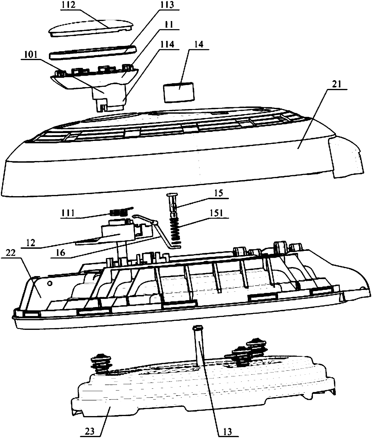
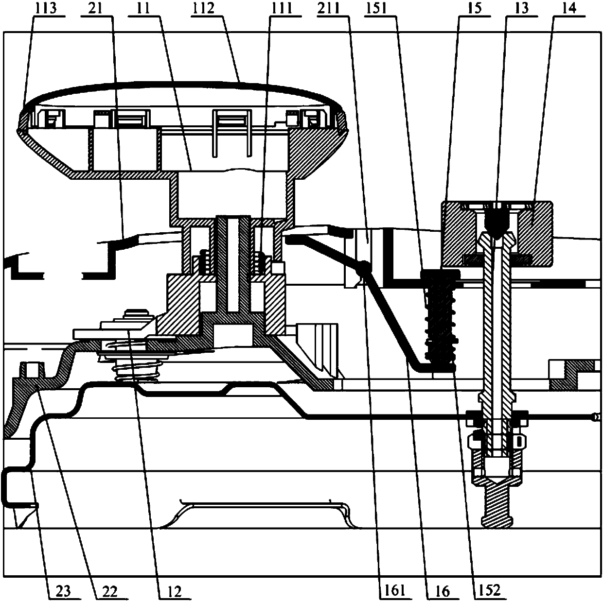
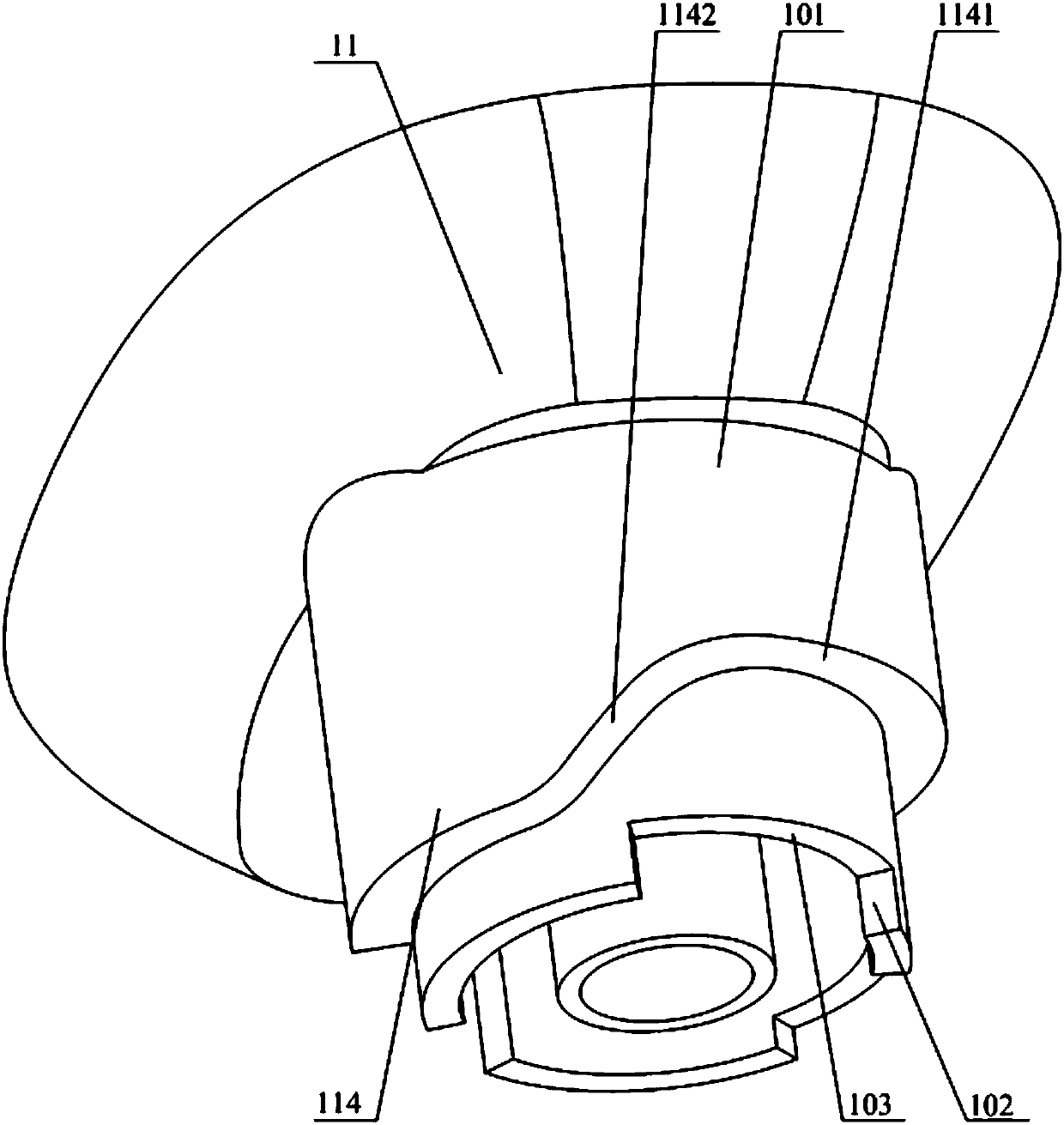
[0027] Please refer to Figure 1 to Figure 3 , figure 1 An exploded view of the structure of the lid assembly of the electric pressure cooker provided by a specific embodiment of the present invention; figure 2 for figure 1 Sectional view of the partial structure of the middle pot cover assembly; image 3 for figure 1 Schematic diagram of the structure of the center handle seat.

[0028] In a specific embodiment, the pot cover assembly provided by the present invent...


PUM


Abstract

The invention discloses a lid assembly. The surface lid is fixedly rotatably provided with a handle base, the inner lid is provided with an open crank which cooperates with the handle base and is in linkage with a steel lid, the surface lid, the inner lid and the steel lid are successively penetrated through an exhaust pipe communicating with the inner cavity of the cooker body; the surface lid is provided with a pressure limiting valve which cooperates with the outer port of the exhaust pipe. One end of the pressure limiting valve is provided with an exhaust ejector rod which is matched with the bottom of the pressure limiting valve, an exhaust lever is arranged between the exhaust ejector rod and the handle base, and a cam is arranged on the handle base in a linkage manner. The cam is provided with a flange cooperating with a force receiving end of the exhaust lever and the biasing end of the exhaust lever is located at the bottom of the exhaust ejector lever. The lid assembly enables simple and efficient remote venting of the electric pressure cooker. The invention also discloses an electric pressure cooker to which the lid assembly is applied.

Description

technical field [0001] The invention relates to the technical field of supporting components of an electric pressure cooker, in particular to a pot cover assembly. The invention also relates to an electric pressure cooker using the pot cover assembly. Background technique [0002] In the working process of the existing electric pressure cooker, the remote exhaust of the electric pressure cooker is generally achieved by setting the exhaust button on the top and realizing the exhaust by jacking up the pressure limiting valve through the transmission structure, or adding other trigger-type additional parts. Or realize exhaust in the process of pressing. Although the above methods can meet the basic exhaust needs, all of the above methods need to increase the exhaust button or other additional parts to achieve, resulting in a more complicated structure for the electric pressure cooker to realize the exhaust, and more difficult equipment assembly. [0003] Therefore, how to eas...

Claims


Application Information

Patent Timeline
Patent Type & Authority Patents(China)
IPC IPC(8): A47J27/086A47J27/08A47J27/09A47J27/56A47J36/38
CPCA47J27/08A47J27/086A47J27/09A47J27/56A47J36/38
Inventor 徐奇欧阳振华易庭增麦焕刘涛张毅鸿
Owner GREE ELECTRIC APPLIANCES INC
Why Eureka
Try Eureka