
Multi-line system and pressure relief control method thereof

A multi-line system and pressure relief technology, applied in the field of multi-line systems, can solve the problems of increased system energy consumption, low system high pressure, and high system high pressure, and achieve the effect of ensuring safe, reliable and stable operation.

Active Publication Date: 2019-04-02
GD MIDEA HEATING & VENTILATING EQUIP CO LTD +1
View PDF6 Cites 0 Cited by
  • Summary
  • Abstract
  • Description
  • Claims
  • Application Information

AI Technical Summary

Problems solved by technology

However, in some cases, if the pressure relief bypass valve is opened, the high pressure of the system will be too low, and if it is not opened, the high pressure of the system will be too high.
Moreover, when selecting the type of pressure relief bypass valve, in order to meet most working conditions, the generally selected pressure relief bypass valve has a relatively large pressure relief capacity. When the pressure relief bypass valve is opened, it is easy to cause compressor failure. The speed increases, resulting in an increase in energy consumption of the system, and most of the electricity is used in the bypass gas circuit, and does not really act on the heating output

Method used


Image

  • Multi-line system and pressure relief control method thereof
  • Multi-line system and pressure relief control method thereof
  • Multi-line system and pressure relief control method thereof

Examples


Embodiment Construction

[0040] Embodiments of the present invention are described in detail below, examples of which are shown in the drawings, wherein the same or similar reference numerals designate the same or similar elements or elements having the same or similar functions throughout. The embodiments described below by referring to the figures are exemplary and are intended to explain the present invention and should not be construed as limiting the present invention.

[0041] The method for controlling pressure relief of a multi-connected system and the multi-connected system according to the embodiments of the present invention are described below with reference to the accompanying drawings.

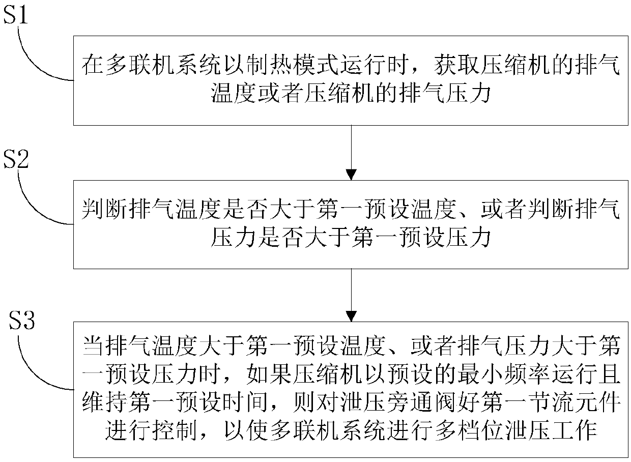
[0042] figure 1 It is a flow chart of a pressure relief control method for a multi-line system according to an embodiment of the present invention.

[0043] In the embodiment of the present invention, such as Image 6 As shown, the multi-split system may include an outdoor unit, a distribution device a...


PUM


Abstract

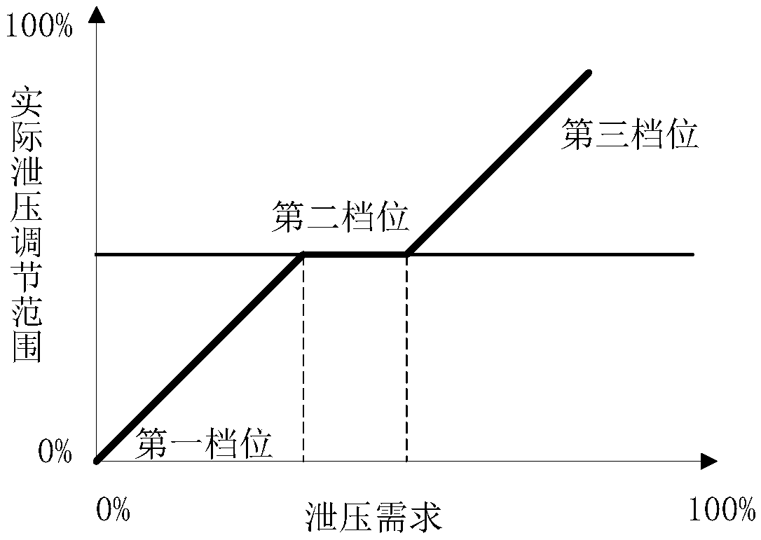
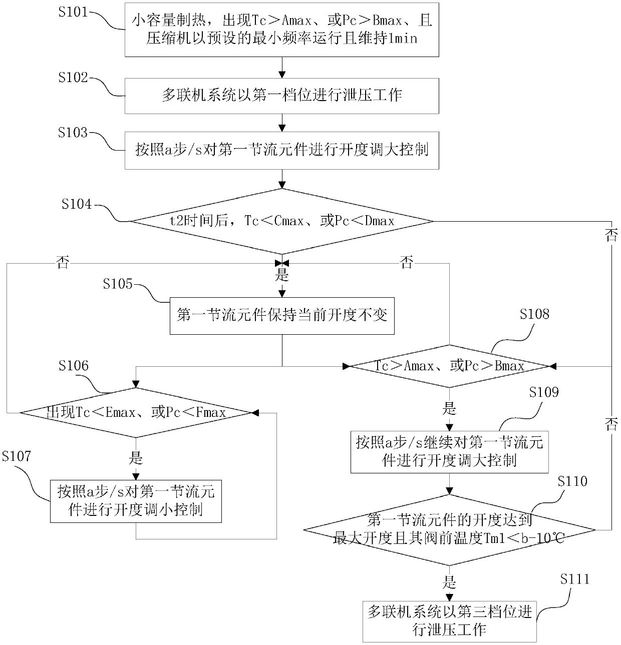
The invention discloses a multiple-in-one system and a pressure relief control method thereof. The method comprises the following steps of: when the multiple-in-one system operates in a heating mode, obtaining a gas exhaust temperature of a compressor or gas exhaust pressure of the compressor; judging whether the gas exhaust temperature is greater than a first preset temperature or not or judging whether gas exhaust pressure is greater than first preset pressure or not; and when the gas exhaust temperature is greater than the first preset temperature or the gas exhaust pressure is greater than the first preset pressure, controlling a pressure relief bypass valve and a first throttling element if the compressor operates with preset minimum frequency for first preset time, thereby enabling the multiple-in-one system to carry out multi-gear pressure relief work. According to the method disclosed by the invention, by controlling the pressure relief bypass valve and the throttling element, the multiple-in-one system can carry out multi-gear pressure relief, so that the pressure relief strategy can be precisely controlled in a variable-capacity mode, and pressure relief needs within a range of 0%-100% are met, and therefore, safe, reliable and stable operation of the system is guaranteed.

Description

technical field [0001] The invention relates to the technical field of air conditioning, in particular to a pressure relief control method for a multi-connection system and a multi-connection system. Background technique [0002] The multi-connected system can perform cooling and heating at the same time, and has a wide range of applications and flexible use. At present, the multi-line system is mainly developing towards the trend of high horsepower and high energy efficiency of a single machine, so the use of large-capacity compressors will become a trend. [0003] However, due to the low-speed drive technology barrier of the inverter compressor, the compressor has a minimum speed limit, and the minimum speed of the large-capacity compressor is still very high for some small-load conditions. Especially for the working conditions where the outside temperature is high and the inside start-up capacity is small, such as high-heat single-start working conditions, even if the sy...

Claims


Application Information

Patent Timeline
Patent Type & Authority Patents(China)
IPC IPC(8): F25B29/00F25B49/02
CPCF25B29/003F25B49/02F25B2313/0231F25B2600/2525F25B2700/1931F25B2700/21152
Inventor 王命仁李元阳
Owner GD MIDEA HEATING & VENTILATING EQUIP CO LTD
Learn More