Positioning and pressing tool for fabricating motor iron core

An iron core and pressing plate technology, applied in the field of positioning and pressing tooling, can solve the problems affecting the electromagnetic and electrical performance of the motor iron core, the quality stability of the product yield and the work reliability, the thickness of the punching sheet, the size of the pressing force, the size of the sheet The gap and uniformity restriction, the verticality of the inner hole surface and the outer surface and the overall surface flatness are not ideal, etc., to achieve the effect of reliable bonding, reliable mechanical strength, reasonable structure and scientific effect between punching sheets

Inactive Publication Date: 2016-12-14
WUXI JUNHONG AUTOMATION TECH
View PDF5 Cites 0 Cited by
  • Summary
  • Abstract
  • Description
  • Claims
  • Application Information

AI Technical Summary

Problems solved by technology

All three have the characteristics of mature technology, convenient operation and low production cost. They are only suitable for making ordinary iron cores with relatively simple structure, relatively thin punching sheets and relatively small volume. In addition, because these production methods all have the characteristics of local point mechanical plus fixed type, the quality of the produced iron core is easily restricted by the thickness of the punching sheet, the size of the pressing force, the gap between the sheets and the uniformity, and because the iron core After the core is formed, the punches are all in a state of local mechanical fastening, so their own stress is always in an uneven state, which affects their own flatness, makes the basic shape of the iron core deviate from the design requirements, and causes uneven gaps between punches , The verticality of the surface of the inner hole and the outer surface and the flatness of the overall surface are not ideal, and even lead to unsatisfactory conditions such as cracking of the motor iron core, local upturning and deformation of the punching sheet, and then affect the electromagnetic and electrical properties of the motor iron core and product yield , quality stability and work reliability, so it is not ideal from the perspective of practicality and economy

Method used


Image

  • Positioning and pressing tool for fabricating motor iron core
  • Positioning and pressing tool for fabricating motor iron core

Examples


Embodiment Construction

[0014] The present invention will be further described below in conjunction with the accompanying drawings and typical embodiments.

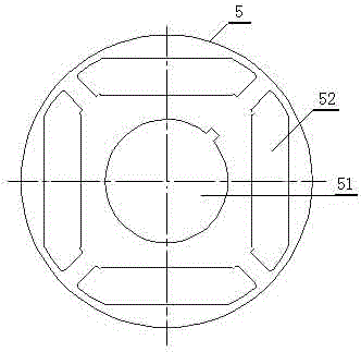
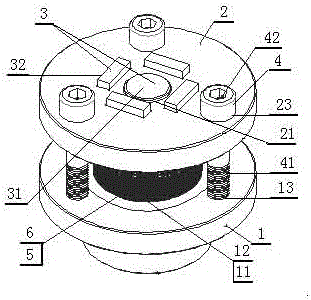
[0015] exist figure 1 and figure 2 Among them, the positioning and pressing tool for making the motor iron core of the present invention includes a lower base plate 1, an upper pressing plate 2, and a limiting member 3 and a fastener 4 arranged between the lower base plate 1 and the upper pressing plate 2, and is characterized in that: The limiting member 3 includes a central axis 31 whose cross section conforms to the shape and size of the central hole 51 on the punching sheet 5 and a side hole limiting strip 32 whose cross section conforms to the shape and size of the peripheral hole 52 on the punching sheet 5; The fastener 4 is composed of a fixed screw rod 41 and a rotatable screw sleeve 42; the lower bottom plate 1 is provided with a central axis mounting hole 11 corresponding to the central hole 51 on the punching piece 5, and is connect...


PUM


Abstract

The invention relates to a positioning and pressing tool for fabricating a motor iron core. The positioning and pressing tool comprises a lower bottom plate, an upper press plate, a limiting member and fastening elements, wherein a central shaft installation hole, a side hole limiting strip arrangement hole and a fixed screw rod installation hole are formed in the lower bottom plate, a central shaft limiting hole, a side hole limiting strip extension hole and rotatable screw sleeve insertion holes are formed in the upper press plate, the limiting member is arranged between the upper bottom plate and the upper press plate and comprises a central shaft and a side hole limiting strip, and the fastening elements are composed of fixed screw rods and rotatable screw sleeves. Since the limiting member is arranged by taking a central hole and surrounding holes in a punch sheet as supports, a limiting punch sheet can be limited in a horizontal direction and a vertical direction and is pressed and reliably limited and shaped by the fastening elements, and the punch sheet is bonded by a high-strength bonding agent which cannot be deformed or cracked after being cured in a high temperature after shaping; and the tool is reasonable and scientific in structure, the fabricated iron core is reliable to shape, and is stable in electromagnetic electrical property, reliable in work and long in service lifetime, the punch sheets are reliably combined and are uniform in stress, the situations such as iron core crack, punch sheet crimping and the like affecting the product quality and the working lifetime can be prevented, and the tool has high practicability.

Description

technical field [0001] The invention relates to the technical field of motor parts manufacturing, in particular to a positioning and pressing tool for making motor iron cores. Background technique [0002] At present, in the manufacture of motor cores, a number of punched and formed punches are usually superimposed and then mechanically solidified to shape the shape. The more commonly used methods are welding, buckle-stacking and punching riveting. Among them: the welding method refers to the method of superimposing the punches with triangular or circular bumps on the edge of the outer circle and then using argon tungsten arc welding to melt the bumps to form a weld to solidify and shape; The method of superimposing and fastening the punching pieces with both buttonholes and buckle plugs on the same position is solidified and formed; the punching riveting method refers to stacking and buckling the punching pieces with pits on each piece and putting them into the positioning ...

Claims


Application Information

Patent Timeline
Patent Type & Authority Applications(China)
IPC IPC(8): H02K15/02
CPCH02K15/02
Inventor 徐晓东秦玉洁
Owner WUXI JUNHONG AUTOMATION TECH
Why Eureka
Try Eureka