
Thrust Reverser Apparatus and Method

A thrust reverser, axial technology, used in the field of aircraft

Active Publication Date: 2016-12-21
THE BOEING CO
View PDF5 Cites 21 Cited by
  • Summary
  • Abstract
  • Description
  • Claims
  • Application Information

AI Technical Summary

Problems solved by technology

[0004] the latter bypass channel thrust reversers have presented several challenges, including attempts to reduce and / or minimize their onerous weight and the adverse consequences of excess drag

Method used


Image

  • Thrust Reverser Apparatus and Method
  • Thrust Reverser Apparatus and Method
  • Thrust Reverser Apparatus and Method

Examples


Embodiment approach

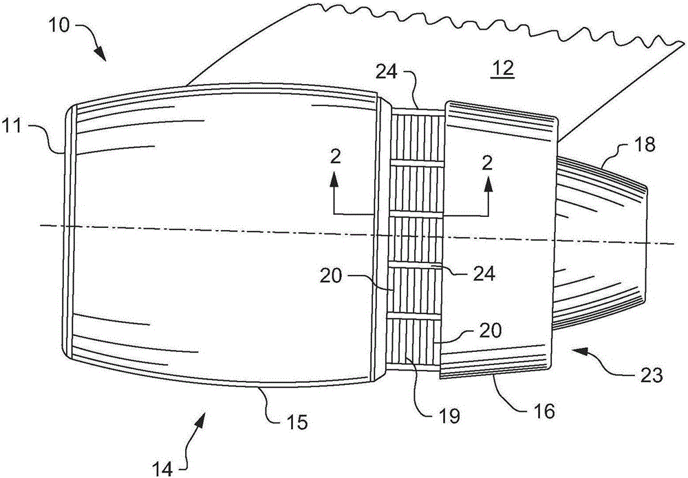
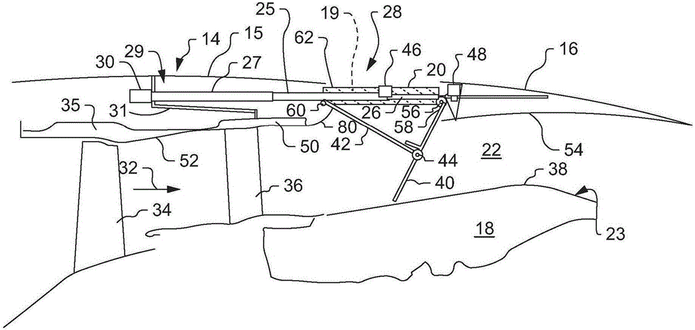
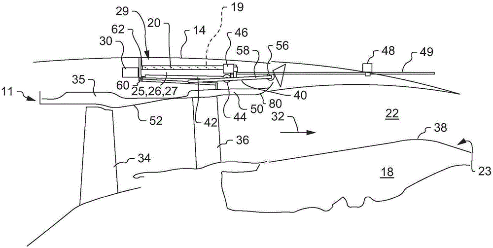
[0048] Item 1. A thrust reverser 28 configured to be located in a turbofan engine nacelle 14 extending around an engine core cowling 18 , the nacelle 14 defining a channel surrounding the engine for receiving a flow of fan bypass air 32 The axially extending bypass passage 22 of the core cowling 18, the thrust reverser 28 includes:

[0049] a translating sleeve 16 movably coupled to the fixed portion 15 of the nacelle 14; and

[0050] choke 40, pivotally coupled to the translating sleeve 16 such that movement of the translating sleeve 16 in an axially rearward direction causes the choke 40 to move rearwardly while maintaining an axial orientation , and wherein, the outer wall 50 of the bypass channel 22 is radially inserted between the choke door 40 and the fan bypass airflow 32 when the choke door 40 is in the retracted position.

[0051] Item 2. The thrust reverser 28 of item 1, wherein the first end of the choke 40 is coupled to the translating sleeve 16 at a first pivot joi...


PUM


Abstract

A thrust reverser is adapted to be fixed within a turbofan engine nacelle that extends substantially about an engine core cowl. The nacelle and engine core cowl together define an axially extending annular duct for receiving an aft flowing fan bypass air stream that is forwardly redirected upon deployment of the thrust reverser. The nacelle includes an axially translating sleeve, circumferentially arranged translating cascade sets, and axially translatable blocker doors adapted to pivot radially inwardly from the translating sleeve to extend at least partially into the fan bypass air stream. A blocker door deployment drag linkage is pivotally coupled to each of the translating sleeve and the blocker doors. When stowed, an axially extending outer wall of the bypass duct is radially interposed between each blocker door and the fan bypass air stream to assure that the blocker doors remain entirely concealed from the fan bypass air stream.

Description

technical field [0001] The present disclosure relates generally to aircraft, and more particularly, to thrust reverser arrangements configured for use on board aircraft. Background technique [0002] Various control devices are used to effectively and efficiently steer the aircraft during all phases of flight. Some control devices are attached directly to the wings of the aircraft, such as ailerons adapted for controlling "roll", ie the rotational movement of the aircraft about its longitudinal axis. Spoilers may also be attached directly to the aircraft wing to reduce wing lift when and as desired, especially during various landing phases of flight. Flaps are usually attached directly to the wings to change their aerodynamic shape in order to ensure stable flight control during slower speeds such as during take-off and landing. [0003] When commercial jets are landing, some form of thrust reverser is usually deployed immediately after actual touchdown in order to reduce ...

Claims


Application Information

Patent Timeline
IPC IPC(8): F02K1/76
CPCF02K1/763F05D2220/323F02K1/72F02K1/827F02C7/24F05D2260/96F05D2260/50Y02T50/60F02K1/70F02K1/766
Inventor 大卫·W·福奇
Owner THE BOEING CO
Learn More