

High-voltage switchgear and its working method
A high-voltage switchgear and switchgear technology, applied in the field of switchgear, can solve the problems of personal injury, easy accidental touch by operators, etc., and achieve the effect of preventing condensation, protecting switchgear, and having good protection effect.
- Summary
- Abstract
- Description
- Claims
- Application Information
AI Technical Summary
Problems solved by technology
Method used
Image

Examples
Embodiment 1
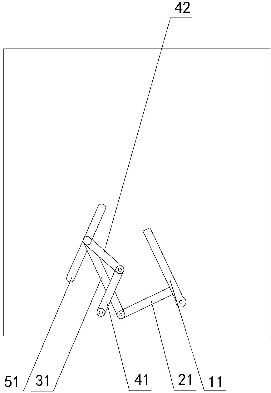
[0051] figure 1 Schematically provides a simplified structural diagram of the high-voltage switchgear of the embodiment of the present invention, as figure 1 As shown, the high-voltage switchgear includes:
[0052] Two wrenches 11, the wrenches are rotatably arranged on the rotating shaft, and the rotating shaft is fixed on the opposite side wall 1;
[0053] Two torsion springs, the torsion springs are fixed between the wrench and the side wall, so that the wrench can return when the external force is removed;
[0054] Two rotating arms 21, the rotating arms are fixed on the wrench; one end of the rotating arm is bent and fixed on the wrench, and the extension of the wrench is bent and fixed on the rotating arm;
[0055] Two link arms 31, one end of the link arm is rotatably arranged on the rotating arm, such as connected by bolts and nuts;
[0056] Two moving parts, the moving parts are located in the through holes or slots 51 inclined from top to bottom and inward on the ...
Embodiment 2
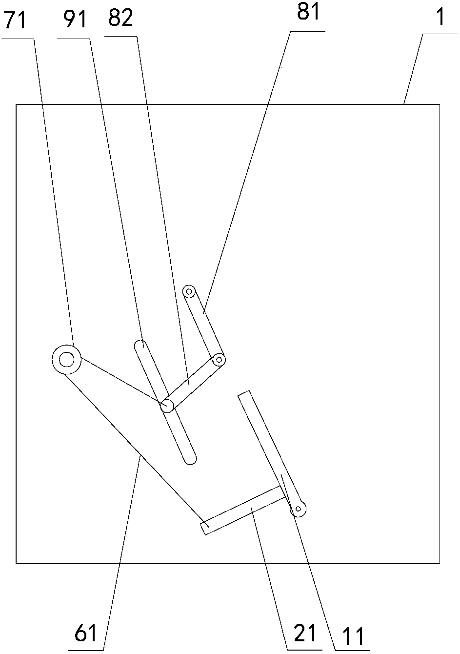
[0072] The high-voltage switchgear of the embodiment of the present invention, such as figure 2 Shown, different from embodiment 1 is:
[0073] 1. The linkage arm is no longer set, and the following structure is adopted:
[0074] two pulleys 71, said pulleys being fixed on the opposite side walls 1;
[0075] Two connecting ropes 61, one end of the connecting rope is fixed on the rotating arm, and the other end goes around the pulley and is fixed on the moving part;
[0076] 2. The upper side of the first shutter is rotatably disposed on the opposite side wall;
[0077] Both ends of the lower side of the second shielding member 42 are fixedly connected to the moving member, and the upper side is rotationally connected to the lower side of the first shielding member 41;
[0078] The through holes or grooves 51 are inclined outward from top to bottom.
[0079] In the working method of the above switch cabinet, when the handcart pushes the wrench to move inward, the rotating ...
Embodiment 3
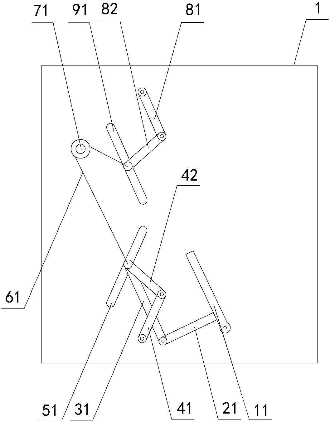
[0081] The high-voltage switchgear of the embodiment of the present invention, such as image 3 Shown, different from embodiment 1 is:
[0082] The switchgear also includes:
[0083] two pulleys 71 fixed on opposite side walls;
[0084] Two connecting ropes 61, one end of the connecting rope is fixed on the part of the moving part passing through the side wall (the connecting rope and the shielding part are respectively on both sides of the side wall), and the other end goes around the pulley and is fixed on an additional on moving parts;
[0085] Two additional moving parts, the additional moving parts are located in the additional inclined limiting through holes or grooves 91 on the opposite side walls; the through holes or grooves are inclined outward from top to bottom ;
[0086] A third shutter 81, the upper side of the third shutter is rotatably arranged on the opposite side wall;
[0087] The fourth shielding part 82, the two ends of the lower side of the fourth sh...
PUM
 Abstract
Description
Claims
Application Information