Switch cabinet with automatic illuminating function

An automatic lighting and switchgear technology, applied in the field of switchgear, can solve the problems of safety accidents, poor light in the switchgear, unclear equipment, etc., and achieve the effect of reducing the probability of safety accidents, preventing condensation, and avoiding personal injury.

Active Publication Date: 2016-12-14
WUHU JINNIU ELECTRIC
View PDF6 Cites 0 Cited by
  • Summary
  • Abstract
  • Description
  • Claims
  • Application Information

AI Technical Summary

Problems solved by technology

The light in the switch cabinet is poor, especially at night. If no additional lighting facilities are provided, the equipment inside cannot be seen clearly, which can easily cause safety accidents

Method used


Image

  • Switch cabinet with automatic illuminating function
  • Switch cabinet with automatic illuminating function
  • Switch cabinet with automatic illuminating function

Examples


Embodiment 1

[0033] figure 1 Schematically provides a simplified structural diagram of the switchgear of the embodiment of the present invention, as figure 1 As shown, the switchgear includes:

[0034] Cabinet body, cabinet door and door frame 161; These parts are all prior art in this field, do not repeat them here;

[0035] Supports 111-112, such as "L" shaped members, are installed inside the door frame;

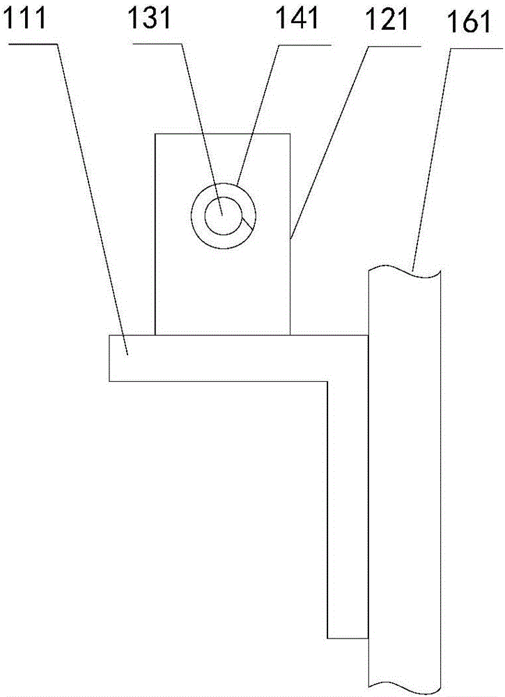
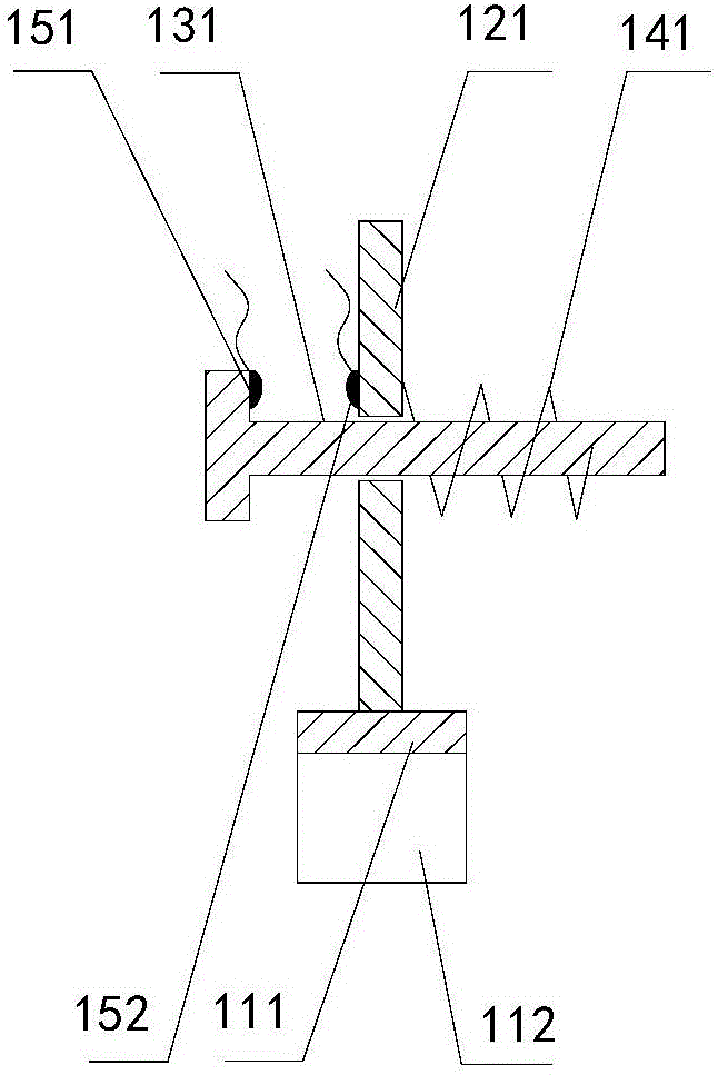
[0036] Figure 2-3 Schematically provides a simplified structural diagram of the switch of the embodiment of the present invention, such as Figure 2-3 As shown, the switch is installed on the support member, and the switch has an operating member that is pushed by the cabinet door to close the switch when the cabinet door is closed, and closes the switch when the cabinet door is opened; the switch includes:

[0037] The mounting plate 121, the mounting plate has a through hole suitable for the operation member to pass through;

[0038] The first conductive part 151, the first co...

Embodiment 2

[0063] An application example of the switchgear according to Embodiment 1 of the present invention.

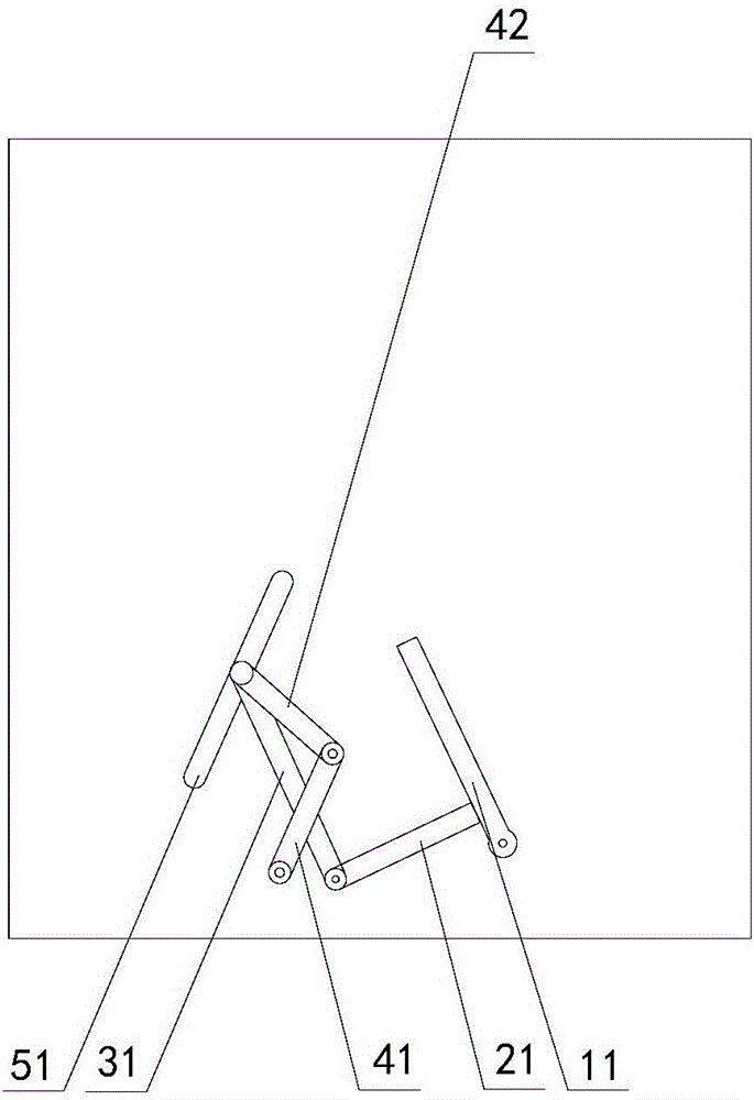
[0064] Such as figure 2 , 3 As shown, in this application example, the support adopts an "L"-shaped member, including a vertical part 12 and a horizontal part 11, the vertical part 12 is installed on the inner wall of the vertical door frame 61; the mounting plate 21 is fixed on the horizontal part 11; the operating part 31 is in a "T" shape, and the radius of the circumscribed circle at the end is greater than the inner diameter of the through hole on the mounting plate; the elastic part 41 uses a spring. The heating element adopts an electric heater; it is installed at the lower part of the inner wall of the switch cabinet; the judging module adopts a judging circuit, which is a prior art in the field and will not be repeated here.

Embodiment 3

[0066] The switchgear of the embodiment of the present invention, as Figure 4 Shown, different from embodiment 2 is:

[0067] 1. The linkage arm is no longer set, and the following structure is adopted:

[0068] two pulleys 71, said pulleys being fixed on the opposite side walls 1;

[0069] Two connecting ropes 61, one end of the connecting rope is fixed on the rotating arm, and the other end goes around the pulley and is fixed on the moving part;

[0070] 2. The upper side of the first shutter is rotatably disposed on the opposite side wall;

[0071] Both ends of the lower side of the second shielding member 42 are fixedly connected to the moving member, and the upper side is rotationally connected to the lower side of the first shielding member 41;

[0072] The through holes or grooves 51 are inclined outward from top to bottom.

[0073] In the working method of the above switch cabinet, when the handcart pushes the wrench to move inward, the rotating arm drives the mov...


PUM


Abstract

The invention provides a switch cabinet with an automatic illuminating function. The switch cabinet comprises a door frame, a cabinet door, a support component, a switch and an illuminating lamp, wherein the support component is arranged on the inner side of the door frame; the switch is arranged on the support component; the switch is equipped with an operation component; the operation component is used for switching on the switch under the driving of the cabinet door when the cabinet door is closed and switching off the switch when the cabinet door is opened; the illuminating lamp is fixed on an inner wall of the switch cabinet; the switch is used for controlling the illuminating lamp to turn on/off. The switch cabinet has the advantage of high safety.

Description

technical field [0001] The invention relates to a switch cabinet, in particular to a switch cabinet with automatic lighting function. Background technique [0002] At present, the basic structure of the switch cabinet is: cabinet body, handcart, and the grounding of the handcart is through the fixed cabinet body. When the handcart enters and pulls out of the cabinet body, the grounding device of the cart cooperates with the grounding device of the handcart. , separation. When the temperature difference between the inside and outside of the switch cabinet is large, condensation will appear in the switch cabinet, which will corrode the equipment in the cabinet and reduce the working performance and service life. The light in the switch cabinet is poor, especially at night. If no additional lighting facilities are provided, the equipment inside cannot be seen clearly, which can easily cause safety accidents. Contents of the invention [0003] In order to solve the above-men...

Claims


Application Information

Patent Timeline
Patent Type & Authority Applications(China)
IPC IPC(8): H02B11/127H02B11/167H02B1/56
CPCH02B1/565H02B11/127H02B11/167
Inventor 刘朝国叶小广彭益峰魏叶林吴燕
Owner WUHU JINNIU ELECTRIC
Why Eureka
Try Eureka