Adjustable switch cabinet

A switchgear, adjustable technology, applied in the field of switchgear, can solve the problems of easy accidental touch by operators, personal injury, etc., and achieve the effect of protecting switchgear, preventing condensation, and good protection effect

Active Publication Date: 2016-12-21
WUHU JINNIU ELECTRIC
View PDF7 Cites 0 Cited by
  • Summary
  • Abstract
  • Description
  • Claims
  • Application Information

AI Technical Summary

Problems solved by technology

When the handcart exits, the high-voltage equipment in the switch cabinet is exposed, and the operator is easy to accidentally touch it, which may cause personal injury

Method used


Image

  • Adjustable switch cabinet
  • Adjustable switch cabinet
  • Adjustable switch cabinet

Examples


Embodiment 1

[0062] figure 1 A schematic structural diagram of a switchgear with a self-sealing function according to an embodiment of the present invention is schematically provided, as shown in figure 1 As shown, the switchgear includes:

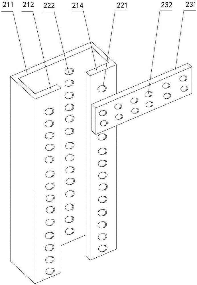
[0063] Cabinet, such as figure 2 As shown, the cabinet includes:

[0064]A vertical member, the horizontal section of the vertical member includes a bottom 211, fixed parts 212, 214 bent twice along the two sides of the bottom, and the distance between the projections of the two fixed parts on the bottom is greater than zero; There are installation holes 221 on the fixed part; there are installation holes 222 in the projection between the two fixed parts of the bottom on the bottom, which is convenient for the connection of two switch cabinets;

[0065] A horizontal piece 231, the horizontal piece has installation holes 232 arranged in the horizontal direction, and has installation holes 232 arranged in the vertical direction at both ends;

[0066...

Embodiment 2

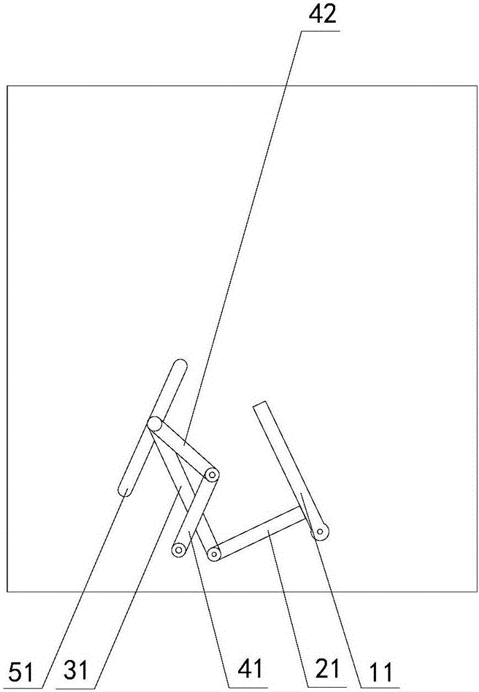
[0096] The switchgear with self-sealing function of the embodiment of the present invention, such as Figure 5 Shown, different from embodiment 1 is:

[0097] 1. The linkage arm is no longer set, and the following structure is adopted:

[0098] two pulleys 71, said pulleys being fixed on the opposite side walls 1;

[0099] Two connecting ropes 61, one end of the connecting rope is fixed on the rotating arm, and the other end goes around the pulley and is fixed on the moving part;

[0100] 2. The upper side of the first shutter is rotatably disposed on the opposite side wall;

[0101] Both ends of the lower side of the second shielding member 42 are fixedly connected to the moving member, and the upper side is rotationally connected to the lower side of the first shielding member 41;

[0102] The through holes or grooves 51 are inclined outward from top to bottom.

[0103] In the working method of the above switch cabinet, when the handcart pushes the wrench to move inward,...

Embodiment 3

[0105] The switchgear with self-sealing function of the embodiment of the present invention, such as Image 6 Shown, different from embodiment 1 is:

[0106] The switchgear also includes:

[0107] two pulleys 71 fixed on opposite side walls;

[0108] Two connecting ropes 61, one end of the connecting rope is fixed on the part of the moving part passing through the side wall (the connecting rope and the shielding part are respectively on both sides of the side wall), and the other end goes around the pulley and is fixed on an additional on moving parts;

[0109] Two additional moving parts, the additional moving parts are located in the additional inclined limiting through holes or grooves 91 on the opposite side walls; the through holes or grooves are inclined outward from top to bottom ;

[0110] A third shutter 81, the upper side of the third shutter is rotatably arranged on the opposite side wall;

[0111] The fourth shielding part 82, the two ends of the lower side of...


PUM


Abstract

The present invention provides an adjustable switch cabinet, wherein the switch cabinet comprises a cabinet body, a cabinet door, and a door frame. The cabinet body forms opposite side walls. The cabinet body comprises a vertical piece, wherein a horizontal cross-section of the vertical piece comprises a bottom part, fixing parts that bend twice along both sides of the bottom part, and a distance of projections of the two fixing parts on the bottom part is greater than zero; and the fixing part is provided with a mounting hole; a horizontal piece, wherein the horizontal piece is provided with mounting holes arranged along a horizontal direction, and is provided with mounting holes arranged along a vertical direction on both ends; a connecting piece, wherein the connecting piece passes through the mounting hole on the horizontal piece and is fixed in the mounting holes arranged in the vertical direction of the horizontal piece; and an installation part, wherein both ends of the installation part are respectively fixed in the mounting holes arranged in the horizontal direction of the horizontal piece by using another disposed connecting piece. The adjustable switch cabinet has advantages of being convenient in assembly, adjustable in position, and flexible.

Description

technical field [0001] The invention relates to a switch cabinet, in particular to an adjustable switch cabinet. Background technique [0002] At present, the basic structure of the switch cabinet is: cabinet body and handcart. The structure that makes up the cabinet is fixed, and once it is fixed, it cannot be changed, and the flexibility is poor. The grounding of the handcart is through the fixed cabinet. When the handcart enters and pulls out of the cabinet, the grounding device of the cart cooperates with and separates from the grounding device of the handcart. When the handcart exits, the high-voltage equipment in the switch cabinet is exposed, and the operator is easy to accidentally touch it, which will cause personal injury. Contents of the invention [0003] In order to solve the shortcomings in the above-mentioned prior art solutions, the present invention provides an adjustable switchgear with convenient assembly, adjustable position and good protection effect...

Claims


Application Information

Patent Timeline
Patent Type & Authority Applications(China)
IPC IPC(8): H02B11/127H02B11/167H02B1/56
CPCH02B1/565H02B11/127H02B11/167
Inventor 刘朝振刘朝锋冯俊黄志才肖吕斌
Owner WUHU JINNIU ELECTRIC
Why Eureka
Try Eureka