A wire cutting fixture

A wire cutting tooling and fixture technology, applied in the field of tooling and fixtures, can solve the problems of manpower and raw material waste, etc.

Active Publication Date: 2017-10-20
FACTORY 5721 OF PLA
View PDF7 Cites 0 Cited by
  • Summary
  • Abstract
  • Description
  • Claims
  • Application Information

AI Technical Summary

Problems solved by technology

[0004] The invention provides a wire cutting fixture, which aims to solve the problems of manpower and raw material waste in the existing collar manufacturing process, so as to achieve the purpose of improving work efficiency and reducing production costs

Method used


Image

  • A wire cutting fixture
  • A wire cutting fixture
  • A wire cutting fixture

Examples


Embodiment Construction

[0030] The present invention will be further described below in conjunction with the accompanying drawings and specific embodiments.

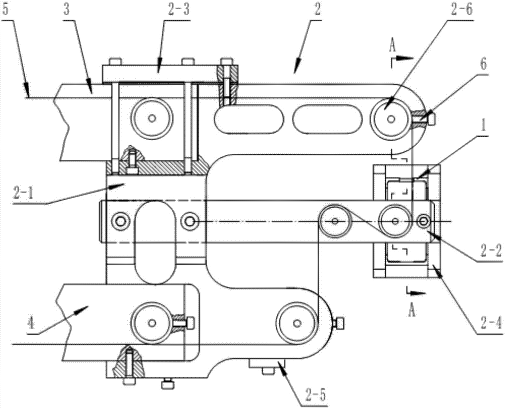
[0031] see image 3 , Figure 4 , Figure 5 , Figure 8 , Figure 9 , Figure 12 , the wire cutting fixture 2 of the present invention includes a tooling bracket 2-1, a middle arm 2-2, a pressing plate 2-3, a workpiece clamping seat 2-4 and a set of guide wheels 2-6; The tooling support 2-1 is fixedly installed on the upper support arm 3 of the wire cutting machine tool through the pressing plate 2-3, and the middle support arm 2-2 is equipped in the middle part of the tooling support 2-1; the middle support arm 2-2 is divided into One-piece structure, consisting of a fixed arm 2-2-1 and a detachable arm 2-2-2 installed on the fixed arm, forming an up and down connection between the fixed arm 2-2-1 and the detachable arm 2-2-2 The guide wheel accommodation cavity 2-2-3, respectively arrange a group of guide wheels 2-6 in the left and righ...


PUM


Abstract

The invention provides a wire cutting tool fixture and belongs to the technical field of wire cutting. The wire cutting tool fixture comprises a tool bracket, a middle support arm, a pressing plate, a workpiece clamping base and a guide wheel component, wherein the workpiece bracket is fixedly arranged on an upper support arm of a linear cutting machine through the pressing plate, and a middle support arm is assembled at the middle of the tool support; the middle support arm is of a split structure and consists of a fixed arm and a detachable arm arranged on the fixed arm; a guide wheel accommodating cavity which is penetrating in the vertical direction is formed between the fixed arm and the detachable arm; the guide wheel accommodating cavity is provided with two groups of guide wheels in left-and-right direction; the center distance H1 of the two groups of guide wheels is greater than the width H of a clamping ring workpiece, i.e., H1 is greater than H; the workpiece clamping base is fixed to a movable arm of the linear cutting machine, and the movable arm of the linear cutting machine is used for driving to realize the horizontal motion in a front-and-back direction and a left-and-right direction. The wire cutting tool fixture can be used for solving the problem of wastes of manpower and materials of an existing clamping ring manufacturing process, and achieving the purpose of improving the working efficiency and lowering the production cost.

Description

technical field [0001] The invention relates to a tooling fixture, in particular to a tooling fixture suitable for performing wire-cutting processing on a clamping structure on a collar, and belongs to the technical field of wire-cutting. Background technique [0002] The collar is one of the important components of the flexible connection of non-metallic conduits. It is widely used in industrial and agricultural production, national defense construction and aviation fields. as attached figure 1 The shown collar 1 is composed of two parts, the left slip 1-1 and the right slip 1-2, and the dovetails that cooperate with each other are set on the end faces of the left slip 1-1 and the right slip 1-2. Slot clamping structure 1-3, and through holes 1-4 are provided on the side walls of the left slip 1-1 and the right slip 1-2. The collar 1 is usually turned into a circular ring blank during manufacturing and processing. Then, the clamping mating surface is processed by milling ...

Claims


Application Information

Patent Timeline
Patent Type & Authority Patents(China)
IPC IPC(8): B23H11/00B23H7/10
CPCB23H7/105B23H11/003
Inventor 胡树欣张龙飞王敬伟张高源王绍增李林张兰英陆升王忠意任飞
Owner FACTORY 5721 OF PLA
Why Eureka
Try Eureka