

Moon cake printing device
A printing and moon cake technology, applied in dough embossing machines, food science, baking, etc., can solve the problems of heavy labor workload, hygienic problems, time-consuming and labor-intensive problems, and achieve the goal of improving work efficiency, reducing work errors and costs Effect
- Summary
- Abstract
- Description
- Claims
- Application Information
AI Technical Summary
Problems solved by technology
Method used
Image

Examples
Embodiment 1
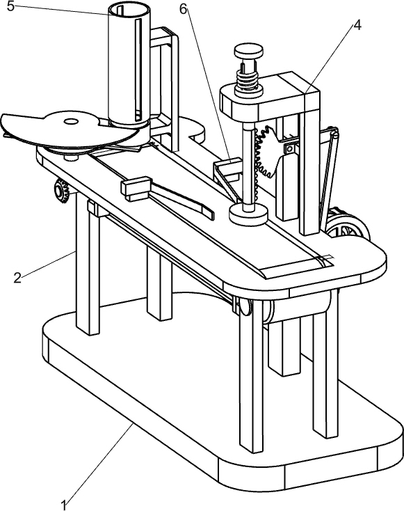
[0058] A moon cake printing device, such as Figure 1-3 As shown, it includes a base 1, a supporting column 2, a motor 41 supporting column 2, a transmission mechanism 4 and a feeding mechanism 5, the upper front side of the base 1 is provided with a mounting column 3, and the upper rear side of the base 1 is connected with a supporting column 2. A transmission mechanism 4 is connected between the column 3 and the top of the support column 2, and a feeding mechanism 5 is connected to the top of the transmission mechanism 4.
[0059] When people need to print moon cakes, the prepared moon cakes are first placed in the feeding mechanism 5, and then the transmission mechanism 4 is started. The transmission mechanism 4 drives the feeding mechanism 5 to rotate intermittently for unloading, and at the same time drives the moon cakes to move to the left intermittently. When the mooncake moves to the designated position, the parts of the transmission mechanism 4 move down to emboss th...
Embodiment 2
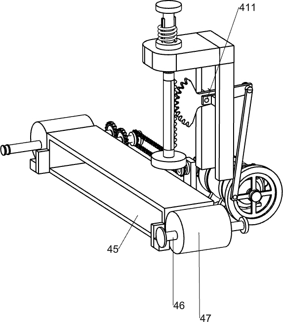
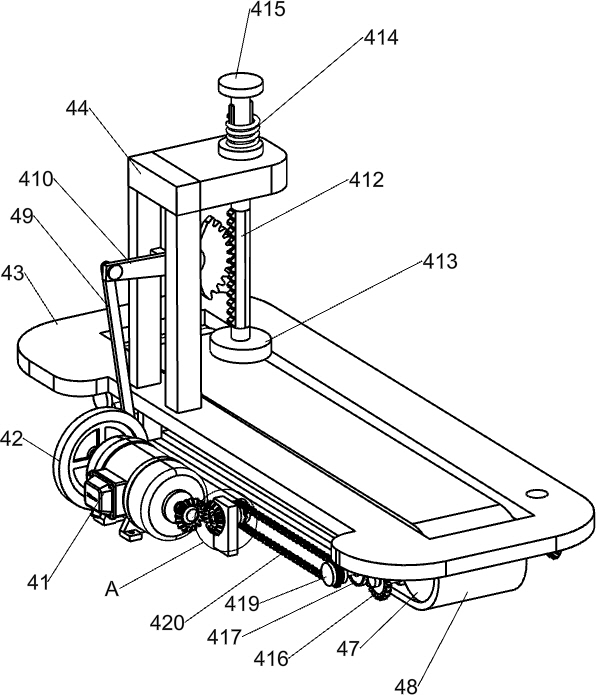
[0061] On the basis of Example 1, such as Figure 4 , 5, 6, and 9, the transmission mechanism 4 includes a motor 41, a transmission wheel 42, a first workbench 43, a second workbench 44, a transmission bottom frame 45, a first transmission shaft 46, a roller 47, a conveyor belt 48, a working Long bar 49, swing gear bar 410, movable bolt 411, rack 412, embossing cover 413, spring 414, fixed bolt 415, full gear 416, missing gear 417, second transmission shaft 418, sprocket wheel 419, chain 420, Sprocket 419 and the first bevel gear set 423, the middle side of mounting column 3 top is provided with motor 41, and the rotation type is connected with rotating shaft 421 on the right side of mounting column 3, is connected with rotating shaft 421 front side and motor 41 output shafts The first bevel gear set 423 is connected with a transmission bottom frame 45 between the upper sides of the support columns 2, and the first transmission shaft 46 is rotatably connected between the fron...
Embodiment 3
[0064] On the basis of Example 2, such as Figure 7-8 As shown, the feeding mechanism 5 includes a fastening nut 51, a second bevel gear set 52, a first rotating disk 53, a rotating connecting rod 54, a second rotating disk 55, a feeding support frame 56 and a feeding pipe 57. The right front side of the top of a workbench 43 is connected with a feeding support frame 56, the rear side of the feeding support frame 56 is connected with a feeding pipe 57, and the lower side of the feeding pipe 57 has a circular groove, and the right rear side of the first workbench 43 is rotationally connected with a Rotate the connecting rod 54, the top of the rotating connecting rod 54 is connected with the second rotating disc 55, the second rotating disc 55 cooperates with the circular groove, the middle part of the rotating connecting rod 54 is connected with the first rotating disc 53, the first rotating disc 53 is connected with the feeding pipe 57 bottom contact, the rotating connecting r...
PUM
 Abstract
Description
Claims
Application Information