Shielding gas knife for laser hybrid welding

A hybrid welding and air knife technology, used in laser welding equipment, welding equipment, metal processing equipment, etc., can solve the problems of fixed product parameters, unfavorable process parameter debugging, complex air knife structure, etc., and achieve the effect of improving the protection effect.

Active Publication Date: 2017-01-04
SHANGHAI JIAO TONG UNIV
View PDF6 Cites 10 Cited by
  • Summary
  • Abstract
  • Description
  • Claims
  • Application Information

AI Technical Summary

Problems solved by technology

[0006] From the analysis of related products at home and abroad, the laserHyrid laser arc composite gun of Fronius Company in Austria is equipped with a laser head protection air knife. The air knife has a compact structure and good protection effect. The internal channel of the bracket of the compound gun is then discharged upwards. Due to the narrow channel, strong howling will be generated during use, which is not conducive to the debugging of process parameters. In the research and development stage, the operator must operate outside the laser protection window during the welding process. Larger ones cause environmental noise pollution. In addition, the structure of the modified air knife is also relatively complicated and expensive, and cannot be used alone
[0007] In addition, the laser hybrid welding and laser brazing laser heads developed by Scansonic Company mentioned by Binzel in Germany are also equipped with laser head air knives, which also have the disadvant

Method used


Image

  • Shielding gas knife for laser hybrid welding
  • Shielding gas knife for laser hybrid welding

Examples


Embodiment Construction

[0035] The present invention will be described in detail below in conjunction with specific embodiments. The following examples will help those skilled in the art to further understand the present invention, but do not limit the present invention in any form. It should be noted that those skilled in the art can make several modifications and improvements without departing from the concept of the present invention. These all belong to the protection scope of the present invention.

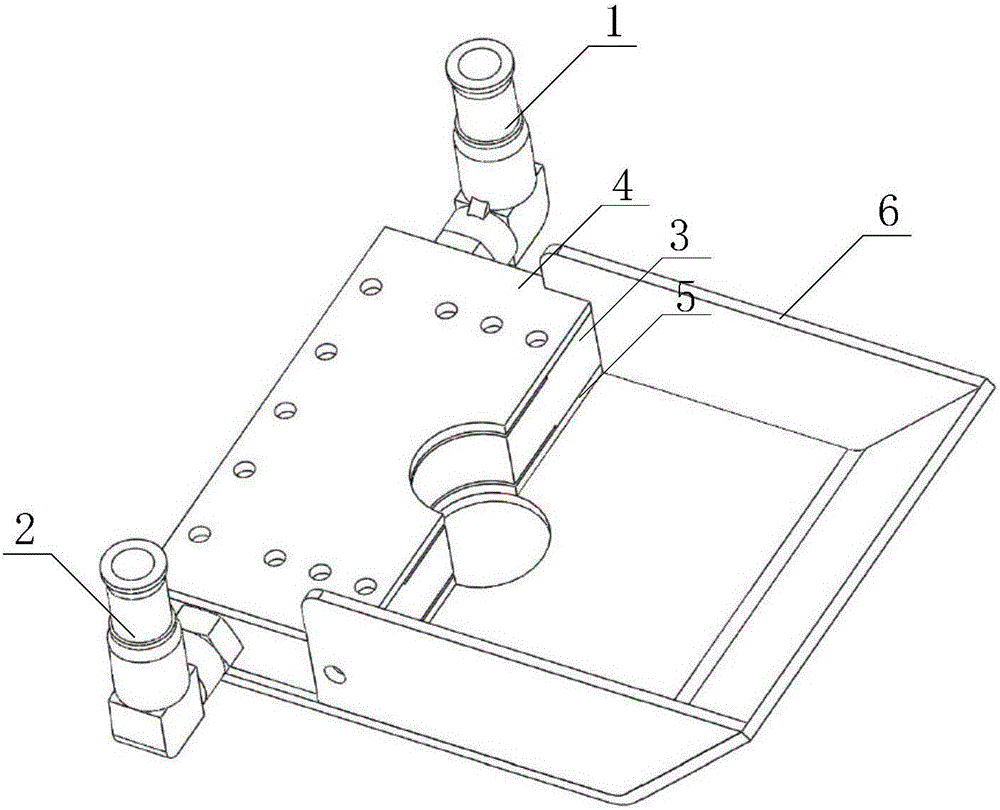
[0036] Such as figure 1 As shown, in this embodiment, the shielded air knife for laser hybrid welding provided by the present invention includes: left air intake pipe joint 1, right air intake pipe joint 2, air knife body 3, air knife body upper cover plate 4, air knife body lower Cover plate 5 and air knife deflector 6;

[0037] The upper end of the left air intake pipe joint 1 is connected to a protective gas pipe, and the upper end of the right air intake pipe joint 2 is connected to another p...


PUM


Abstract

The invention provides a shielding gas knife for laser hybrid welding. The shielding gas knife comprises a left gas inlet pipe joint, a right gas inlet pipe joint, a gas knife body, an upper gas knife body cover plate and a lower gas knife body cover plate; the lower end of the left gas inlet pipe joint is communicated with the left end of a gas inlet flow channel formed in the gas knife body, the lower end of the right gas inlet pipe joint is communicated with the right end of the gas inlet flow channel formed in the gas knife body, the gas inlet flow channel is communicated with compressed gas flow jetting channels of the gas knife body, and the compressed gas flow jetting channels penetrate through the inner side face of the gas knife body to extend out. According to the shielding gas knife, the gas pipe joints can be connected with a shielding gas pipe with the diameter of 12 mm, large flow is introduced by the gas knife body, gas which is compressed through gas guide holes and sped up is large in flow and high in pressure, the gas passes through the first compressed gas flow jetting channel and the second compressed gas flow jetting channel and then uniformly forms a high-speed surface body cutting protection window, and therefore the phenomenon that dust, spatter and the like on the surface of a workpiece penetrate through the protection window to enter a laser processing head in the hybrid welding process can be effectively prevented.

Description

technical field [0001] The invention relates to the field of laser welding manufacturing technology, in particular to a laser processing head protection system using compressed air as an air curtain for laser wire-filling welding or laser arc hybrid welding of high-precision manufacturing, and a laser hybrid welding protective air knife. Background technique [0002] Due to its high energy density, low heat input, small welding deformation, high welding efficiency and good welding quality, laser welding has been widely used and promoted in important fields of the national economy such as automobiles, shipbuilding, aviation and aerospace, and nuclear power. [0003] However, pure laser self-fluxing welding requires high processing and assembly of the workpiece to be welded, and the bridging ability of the weld seam is poor, while laser-filled wire welding, laser-TIG arc hybrid welding or laser-MAG arc hybrid welding, additionally add The welding wire is used to fill the weld ...

Claims


Application Information

Patent Timeline
IPC IPC(8): B23K26/346B23K26/348B23K26/70
CPCB23K26/346B23K26/348B23K26/702
Inventor 张轲张悦李铸国
Owner SHANGHAI JIAO TONG UNIV
Why Eureka
Try Eureka