A high anti-loosening spin riveting blind rivet

A core blind rivet and mandrel technology, applied in the direction of rivets, etc., can solve the problems of connection plate damage, large external force, falling off, etc., and achieve the effect of avoiding fastening accidents, loosening or even falling off.

Active Publication Date: 2018-05-25
AEROSPACE PRECISION PROD INC LTD
View PDF5 Cites 0 Cited by
  • Summary
  • Abstract
  • Description
  • Claims
  • Application Information

AI Technical Summary

Problems solved by technology

[0003] When installing blind rivets, the blind rivets need to rely on riveting tools to apply push and pull force to the blind rivets at the same time, and rivet the rivets to the connected plate. Due to the large external force required in the deformation process of the blind rivet, and the connected plate Simultaneously subjected to axial thrust and tension, it is easy to cause damage to the thinner connected plate
[0004] The spin riveting type blind rivet can convert the driving force of rotation into the axial forward power during installation, avoiding the situation that the thinner connected plate is easily damaged, but after the spin riveting type blind rivet is installed, its The fit of the thread is easy to loosen or even fall off under the action of vibration, causing fastening accidents

Method used


Image

  • A high anti-loosening spin riveting blind rivet
  • A high anti-loosening spin riveting blind rivet
  • A high anti-loosening spin riveting blind rivet

Examples


Embodiment Construction

[0022] The invention will be further described below in conjunction with the accompanying drawings.

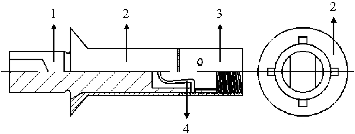
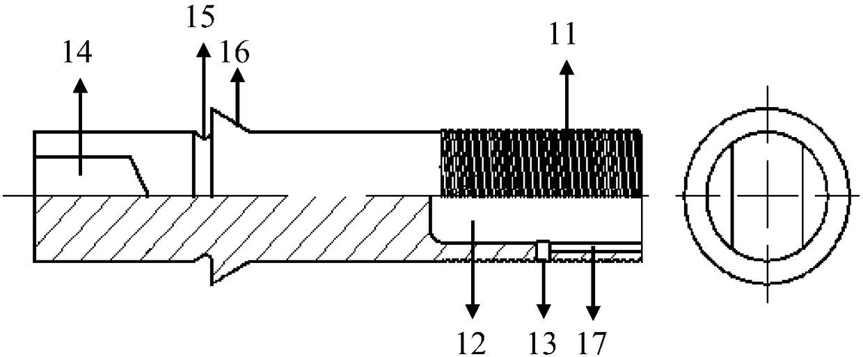
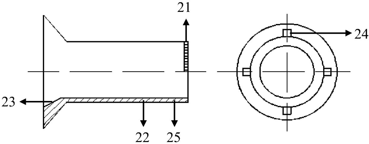
[0023] An embodiment of the inventive structure of the present invention is as figure 1 As shown, it includes a core rod 1, a nail sleeve 2, a nut 3 and a U-shaped spring 4; the outer surface of the tail of the core rod 1 is provided with a threaded section 11, and the tail of the threaded section 11 is covered with all the parts that can be matched and engaged with it. The nut 3; the end surface of the tail part of the core rod 1 is provided with a cavity 12 inwardly along the axial direction, and the inner wall of the cavity 12 is provided with a clamping hole 13 which is connected to the outside symmetrically around the axis, and the U-shaped spring 4 is The compressed state is fixed in the cavity 12, and the two ends of the U-shaped spring 4 are provided with clamping feet 41 outward, and the clamping feet 41 are respectively clamped in the clamping holes 13 of the core ro...


PUM


Abstract

The invention provides a blind rivet. The blind river comprises a core rod, a rivet sleeve, a screw nut and an U-shaped spring, wherein the tail part of the core rod is provided with a thread section, and the screw nut is sheathed on the tail part of the thread section; the end surface of the tail part of the core rod is inwards provided with a cavity along the axial direction, clamping holes are symmetrically formed in the inner wall of the cavity and are communicated with outside, the U-shaped spring is fixedly arranged in the cavity in a compressing way, the two end parts of the U-shaped spring are outwards provided with clamping pins, and the clamping pins are respectively clamped into the clamping holes of the core rod; the inner wall of the screw nut is symmetrically provided with a concave groove or a through groove around the axis; the end surface of the head part of the screw nut is provided with a first sawtooth section around the axis; the rivet sleeve is sheathed on the core rod, the end surface of the tail part of the rivet sleeve is provided with a second sawtooth section around the axis, and the second sawtooth section is engaged with the first sawtooth section; the part, near the end surface of the tail part, of the rivet sleeve is provided with a local annealing section. The blind rivet has the advantage that the installation reliability without loosening is realized.

Description

technical field [0001] The invention belongs to the technical field of fasteners, and in particular relates to a high anti-loosening spin riveting blind rivet. Background technique [0002] In the design process of high-end equipment such as aerospace, considering the factors of volume and weight, the structural design is generally relatively compact. The connection and installation space of these compactly designed structural parts is relatively narrow. It needs to be installed on both sides, and cannot meet the installation requirements of these occasions. Therefore, in these places where the installation space is relatively narrow and it is not convenient for double-sided operation, riveting is generally used. The riveting method used in structural joints is generally blind rivets. Blind rivets have the characteristics of light weight, more reliable connection, high strength, convenient and quick installation, etc., and have been widely used in various aerospace vehicles...

Claims


Application Information

Patent Timeline
Patent Type & Authority Patents(China)
IPC IPC(8): F16B19/10
CPCF16B19/10
Inventor 桂林景马玲林忠亮万冰华黄金湖单垄垄徐国琦张晓玲
Owner AEROSPACE PRECISION PROD INC LTD
Why Eureka
Try Eureka