Tunnel energy pipe piece prefabrication and connection method applied to shield construction

A technology of shield segment and connection method, which is applied in the direction of strengthening and forming, can solve the problems of difficult to achieve the expected effect, inconvenient on-site operation, long construction period, etc., to improve the problem of thermal pollution, broaden the scope of application, and ensure the quality of construction Effect

Pending Publication Date: 2020-03-24
QINGDAO TECHNOLOGICAL UNIVERSITY
View PDF3 Cites 0 Cited by
  • Summary
  • Abstract
  • Description
  • Claims
  • Application Information

AI Technical Summary

Problems solved by technology

However, the inventor found in the research that shield technology has been widely used in the construction of subway tunnels, and the shield section occupies a very large part of the entire subway tunnel section, and the capillary heat exchanger is used as the front-end heat exchanger. The laying is applied to tunnels dug by the mining method. There is no clear laying method in the shield section, which limits the popularization of subway source heat pumps that use capillary heat exchangers as front-end heat exchangers.
Capillary heat exchangers are laid and installed by workers one by one during the construction and installation process. The construction period is long, and the on-site operation is extremely inconvenient. It is easy to damage the capillary tubes, and the inside is prone to blockage. The manpower loss is large, and the construction quality cannot be guaranteed.

Method used


Image

  • Tunnel energy pipe piece prefabrication and connection method applied to shield construction
  • Tunnel energy pipe piece prefabrication and connection method applied to shield construction
  • Tunnel energy pipe piece prefabrication and connection method applied to shield construction

Examples


Embodiment 1

[0041] Attached below Figure 1-Figure 3 The present invention is described in detail, specifically, the structure is as follows:

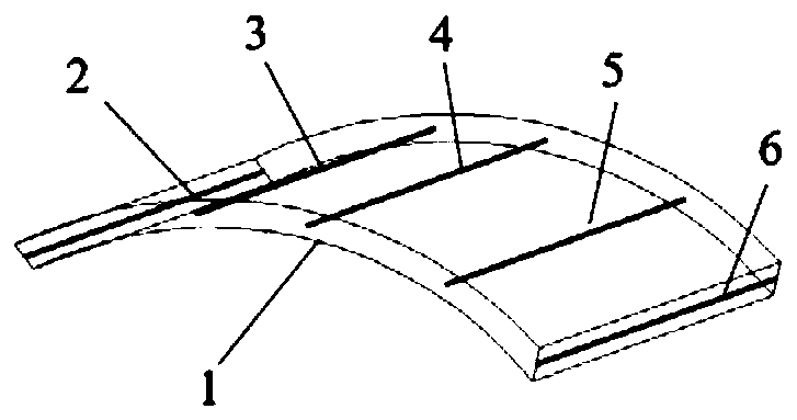
[0042] This embodiment provides a tunnel energy segment prefabrication method applied to shield tunneling construction. The steps are as follows: First, a plurality of steel bars are evenly added and welded at the set position of the reinforcement cage 1. In this embodiment, as figure 1 As shown, five reinforcement bars are welded on the reinforcement cage 1, that is, the first reinforcement bar 2 welded to the middle position of one end of the reinforcement cage 1, the fifth reinforcement bar 6 welded to the middle position of the other end of the reinforcement cage 1, and the fifth reinforcement bar 6 welded to the inside of the reinforcement cage 1 The second steel bar 3, the third steel bar 4 and the fourth steel bar 5.

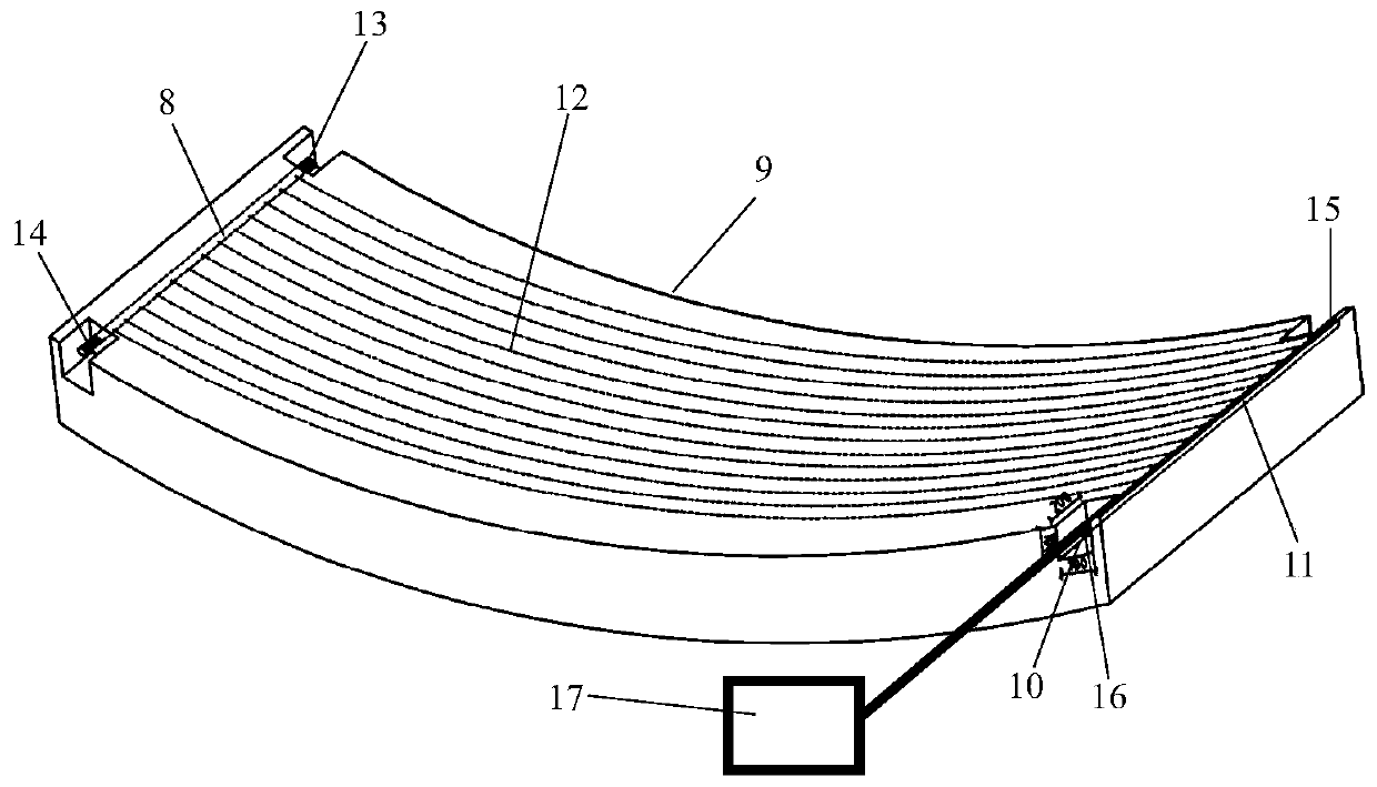
[0043]Select the capillary heat exchanger 12 whose specifications are slightly smaller than the steel cage 1, wherein the ...

Embodiment 2

[0050] This embodiment provides a tunnel energy segment prefabrication method applied to shield tunneling construction, such as Figure 4 As shown in Fig. 5, respectively add and weld a reinforcing bar (the sixth reinforcing bar 21, the seventh reinforcing bar 22) at the two ribs of reinforcing cage 1, the main water supply pipe 11 is bound on the sixth reinforcing bar 21, and the return water main pipe 8 is bound on the second Seven steel bars 22 on.

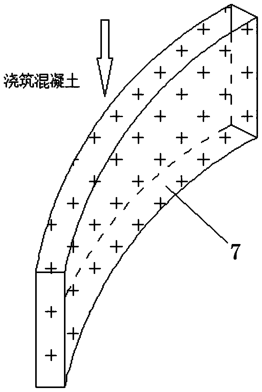
[0051] Before pouring, insert the prefabricated parts, use the shield segment mold 7 to set the second groove 23 that allows the connection of adjacent capillary tubes, the opening side of the second groove 23 is located at the end of the shield segment mold 7, other steps It is the same as the first embodiment, and will not be repeated here.

Embodiment 3

[0053] This embodiment provides a tunnel energy segment connection method applied to shield tunneling construction, as shown in Figure 6(a)-6(b), the capillary trunks between the shield segments 9 are connected by straight seams connected to each other in a way. Before connecting, remove the sealing cover at the dry pipe joint, clean up the cement and other debris on the exposed dry pipe joint, put the adjacent dry pipe joint 20 into the sleeve 19, and use the rubber sealing ring for sealing to avoid There is a leak at the capillary connection 18.

[0054] During construction, every time three shield segments 9 are laid, a pressure test is carried out on the laid capillary. After confirming that there is no leakage at the joint 18, the groove at the joint 18 is filled with concrete to further reduce the joint connection of the main pipe. potential leakage hazards.

[0055] Such as Figure 7(a)-7(b) As shown, after the laying of the shield segment 9 is completed, the return ...


PUM


Abstract

The invention discloses a tunnel energy pipe piece prefabrication and connection method applied to shield construction. The problems that in the prior art, capillary pipes are prone to being damaged,blocking is prone to happening inside, and the construction period is long are solved. A capillary pipe heat exchanger is prefabricated, operation is simple, manual consumption is reduced, and construction quality is reliable. According to the technical scheme, the method comprises the following steps that the set position of a reinforcement cage is welded, and the reinforcement cage is used for fixing steel bars of the capillary pipe heat exchanger; the capillary pipe heat exchanger matched with the sizes of the steel bars is placed in the reinforcement cage and is fixed; inlets and outlets of dry pipes of the capillary pipe heat exchanger are closed under pressure, the reinforcement cage is placed in a mold, concrete is poured, and standing is carried out for a set time so that concreteis solidified; and seepage and blocking detection is carried out on the capillary pipe heat exchanger, and after it is confirmed that the capillary pipe heat exchanger is free of seepage and blocking,the exposed water supply and return dry pipes of the capillary pipe heat exchanger are sealed.

Description

technical field [0001] The invention relates to the technical field of tunnel construction, in particular to a tunnel energy segment prefabrication and connection method applied to shield tunneling construction. Background technique [0002] Subway source heat pumps using capillary heat exchangers as front-end heat exchangers have significant advantages in terms of economy, performance, and environmental protection. However, the inventor found in the research that shield technology has been widely used in the construction of subway tunnels, and the shield section occupies a very large part of the entire subway tunnel section, and the capillary heat exchanger is used as the front-end heat exchanger. Laying is applied to tunnels excavated by mining methods. There is no clear laying method in the shield section, which limits the popularization of subway source heat pumps using capillary heat exchangers as front-end heat exchangers. The capillary heat exchanger is laid and inst...

Claims


Application Information

Patent Timeline
Patent Type & Authority Applications(China)
IPC IPC(8): B28B21/60
CPCB28B21/60
Inventor 季永明胡松涛刘国丹佟振童力
Owner QINGDAO TECHNOLOGICAL UNIVERSITY
Why Eureka
Try Eureka