Positioning device capable of positioning multiple electronic components at same time and operation equipment adopting same positioning device

A technology of electronic components and positioning devices, which is applied in the directions of measuring devices, measuring device casings, and parts of electrical measuring instruments, etc., can solve problems such as deviation errors, inability to perform operations effectively, and reduce production efficiency.

Inactive Publication Date: 2017-01-04
HON PRECISION INC
View PDF10 Cites 5 Cited by
  • Summary
  • Abstract
  • Description
  • Claims
  • Application Information

AI Technical Summary

Problems solved by technology

[0004] 1. There is a gap between the storage tank 111 of the tray 11 and the electronic component 12, so that the electronic component 12 drifts arbitrarily in the storage tank 111, causing the center position of the electronic component 12 to deviate from the center position of the storage tank 111 Error, when the pick-and-place device 131 of the transfer device 13 takes out the electronic components 12 that are offset and placed on the tray 11, and transfers them to the test seat 14, it will be due to the center position of the electronic component 12 relative to the test seat 14. The center position has a deviation error, so that the pick-and-place device 131 cannot accurately move the electronic component 12 into the test socket 14 to perform the test operation
[0005] 2. Since the electronic components 12 will be d

Method used


Image

  • Positioning device capable of positioning multiple electronic components at same time and operation equipment adopting same positioning device
  • Positioning device capable of positioning multiple electronic components at same time and operation equipment adopting same positioning device
  • Positioning device capable of positioning multiple electronic components at same time and operation equipment adopting same positioning device

Examples


Embodiment Construction

[0058] In order to make your examiner further understand the present invention, hereby give a preferred embodiment and cooperate with the drawings, as follows in detail:

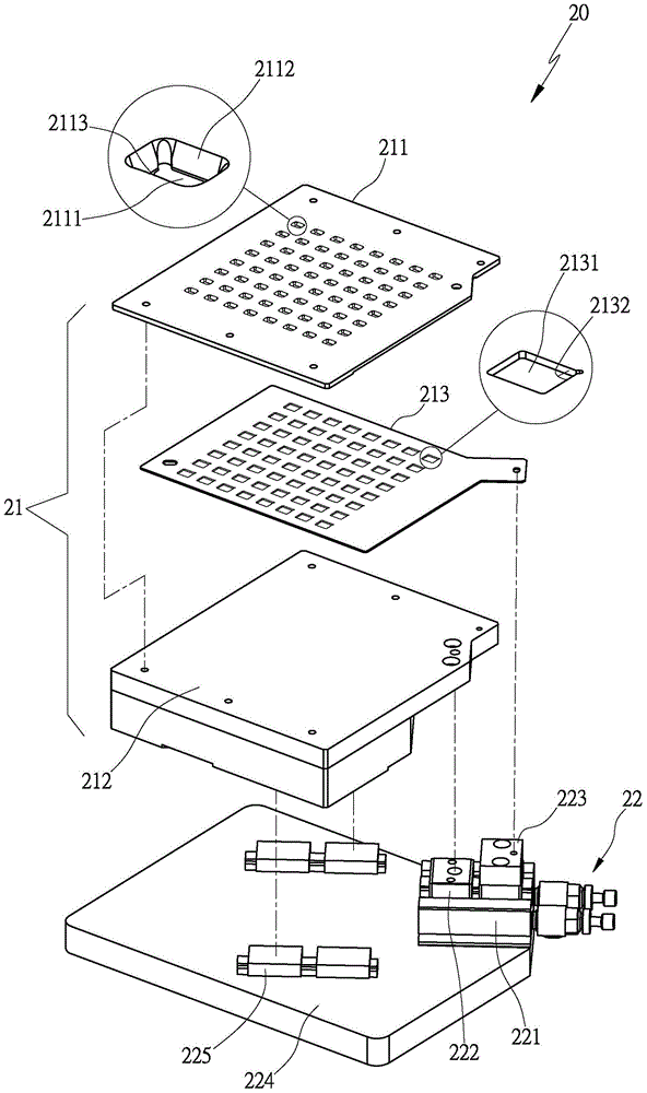
[0059] see image 3 , Figure 4 The positioning device 20 of the present invention includes a positioning mechanism 21 and a driving mechanism 22. The positioning mechanism 21 is provided with a plurality of grippers, and the grippers are provided with a plurality of abutting parts that can be positioned against a plurality of electronic components. Further, The actuation mode of the positioning mechanism 21 can be divided into a single-action pushing method and a double-action pushing method. When the positioning mechanism 21 adopts a single-action pushing method, it can be configured with a fixed clamp and a movable clamp. The movable clamp is opposite to the The displacement of the fixed clamping device enables the fixed clamping device and the movable clamping device to clamp and position multiple elect...


PUM


Abstract

The invention provides a positioning device capable of positioning multiple electronic components at the same time. The positioning device comprises a positioning mechanism and a driving mechanism. The positioning mechanism is provided with a plurality of clamping devices, and each clamping device is provided with a plurality of abut-against parts for abutting against multiple electronic components. The driving mechanism is provided with at least one driving source and is used for driving the plurality of clamping devices of the positioning mechanism to generate relatively-oblique displacement, and thus the plurality of abut-against parts of each clamping device push the multiple electronic components at the same time and abut against angle parts of the multiple electronic components, and the plurality of clamping devices can clamp and position the multiple electronic components, and prevent the multiple electronic components from being drifted at will. The positioning device can be used for positioning the multiple electronic components at the same time at a time, reference parts of the electronic components are enabled to be fixed at preset reference positions, and relative positions of centers of the electronic components are fixed when a pick-and-place device of a transfer device carries out picking and placing, and thus the electronic components can be accurately transferred and placed in an accommodation tank of a bearing container, and the positioning efficiency and the practical benefits of operation quality are improved.

Description

technical field [0001] The invention relates to a positioning device capable of centrally positioning a plurality of electronic components at one time so that a transfer device can accurately place the electronic components into accommodating grooves of a holder, thereby improving positioning efficiency and operation quality. Background technique [0002] Nowadays, electronic components are actively developing towards small, light, thin, and small volumes, and multiple electronic components are contained in holders such as trays or stages. Please refer to figure 1 , taking the tray 11 with a plurality of accommodating grooves 111 as an example, in order for the tray 11 to allow the electronic components 12 to move in or out of the accommodating grooves 111 smoothly, there must be a gap between the accommodating grooves 111 of the tray 11 and the electronic components 12 There is a gap, and the existence of this gap will cause the electronic component 12 to drift arbitrarily ...

Claims


Application Information

Patent Timeline
IPC IPC(8): G01R1/02G01R1/04G01R31/01
Inventor 陈振元
Owner HON PRECISION INC
Why Eureka
Try Eureka