AI technical title is built by Patsnap AI team. It summarizes the technical point description of the patent document.
A detection device and sub-surface technology, which is applied in the electronic field, can solve the problems of not being able to meet diverse needs, single structure of optical detection devices, etc., and achieve the effect of realizing diversified designs
Active Publication Date: 2019-02-05
LENOVO (BEIJING) LTD
View PDF6 Cites 0 Cited by
Summary
Abstract
Description
Claims
Application Information
AI Technical Summary
This helps you quickly interpret patents by identifying the three key elements:
Problems solved by technology
Method used
Benefits of technology
Problems solved by technology
[0005] Embodiments of the present invention provide a detection device and electronic equipment, which are used to solve the technical problem that the optical detection device in the prior art has a single structure and cannot meet diversified requirements, and realize the technical effect of the diversified design of the optical detection device
Method used
Image
Click on the blue label to locate the original text in one second.
Reading with bidirectional positioning of images and text.
Examples
Embodiment 1
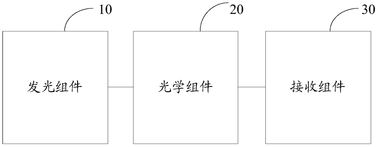
[0049] Please refer to figure 1 , is a functional block diagram of the detection device in the embodiment of the present application.
[0050] The detection device can be a separate optical detection device, such as fingerprint detection, or other detection devices with fingerprint detection functions, such as notebook computers, mobile phones, ID cards, etc. with fingerprint collection functions. Of course, other texture detections may also be used, such as texture detection of cultural relic devices. The detection device includes:
[0051] a light emitting component 10, configured to emit initial light in a first direction;
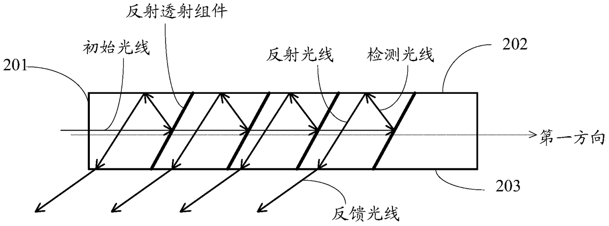
[0052] Optical assembly 20, wherein, the schematic diagram before and after the propagation of the initial light through the optical assembly 20 is as figure 2 As shown, wherein the optical assembly 20 includes five prisms. Specifically, it is at least partially arranged in the irradiation area of the initial light, and the initial light enters t...
Embodiment 2
[0092] Please refer to Figure 6 , a functional block diagram of an electronic device provided in an embodiment of the present application, such as a notebook computer, a mobile phone, an ID card, a wearable device, etc. that include an optical detection device. The electronic equipment includes:
[0093] The detection device 60, wherein the detection device 60 includes a light-emitting component for emitting an initial light in a first direction; an optical component is at least partially arranged in the irradiation area of the initial light, and the initial light is emitted by the first light of the optical unit. One side is incident on the optical unit; wherein, the initial light is based on the optical unit to form a detection light towards a second direction, the second surface of the optical component is located in the second direction, and the first surface and The second surface is different; the receiving component is at least partly arranged in the irradiation are...
PUM
Abstract
The invention discloses a detection device and electronic equipment. The detection device comprises a light emitting module, an optical module and a receiving module, wherein the light emitting module is used for emitting initial light in a first direction; at least part of the optical module is arranged in an irradiation area of the initial light, the initial light is incident to the optical module via the first surface of the optical module, the initial light forms detection light facing a second direction based on the optical module, the second surface of the optical module is located in the second direction, and the first surface is different from the second surface; at least part of the receiving module is arranged in an irradiation area of feedback light for receiving the feedback light emergent from a third surface and facing a third direction, and the feedback light is light formed when the detection light is reflected on the second surface; and the optical module comprises an adjacently-arranged prism set, the prism set comprises N prisms, and the N prisms are arranged adjacently in the first direction.
Description
technical field [0001] The invention relates to the field of electronic technology, in particular to a detection device and electronic equipment. Background technique [0002] Because optical detection technology has the advantages of non-contact, fast measurement speed, and high precision, optical detection devices based on optical detection technology are widely used in various fields of daily life, such as biological texture collection and recognition. [0003] In the process of inventing the technical solutions in the embodiments of the present application, the inventors of the present application found that the above-mentioned prior art has at least the following technical problems: [0004] In the prior art, it is found that the structure of the optical detection device provided in the prior art is simple, so the optical detection device in the prior art has the technical problem of being single in structure and unable to meet various requirements. Contents of the in...
Claims
Application Information
Patent Timeline
Application Date:The date an application was filed.
Publication Date:The date a patent or application was officially published.
First Publication Date:The earliest publication date of a patent with the same application number.
Issue Date:Publication date of the patent grant document.
PCT Entry Date:The Entry date of PCT National Phase.
Estimated Expiry Date:The statutory expiry date of a patent right according to the Patent Law, and it is the longest term of protection that the patent right can achieve without the termination of the patent right due to other reasons(Term extension factor has been taken into account ).
Invalid Date:Actual expiry date is based on effective date or publication date of legal transaction data of invalid patent.

