A rectifier circuit with band-pass characteristic and wide input power range

A technology of rectification circuit and band-pass characteristics, which is applied in the field of microwave energy transmission systems, can solve the problems of widening the input power range and realizing band-pass characteristics, and achieves the effect of high-efficiency rectification

Active Publication Date: 2019-08-02
SYSU CMU SHUNDE INT JOINT RES INST +1
View PDF4 Cites 0 Cited by
  • Summary
  • Abstract
  • Description
  • Claims
  • Application Information

AI Technical Summary

Problems solved by technology

Considering the practical application aspect, a method has never been proposed that can broaden the input power range and realize the bandpass characteristic at the same time

Method used


Image

  • A rectifier circuit with band-pass characteristic and wide input power range
  • A rectifier circuit with band-pass characteristic and wide input power range
  • A rectifier circuit with band-pass characteristic and wide input power range

Examples


Embodiment 1

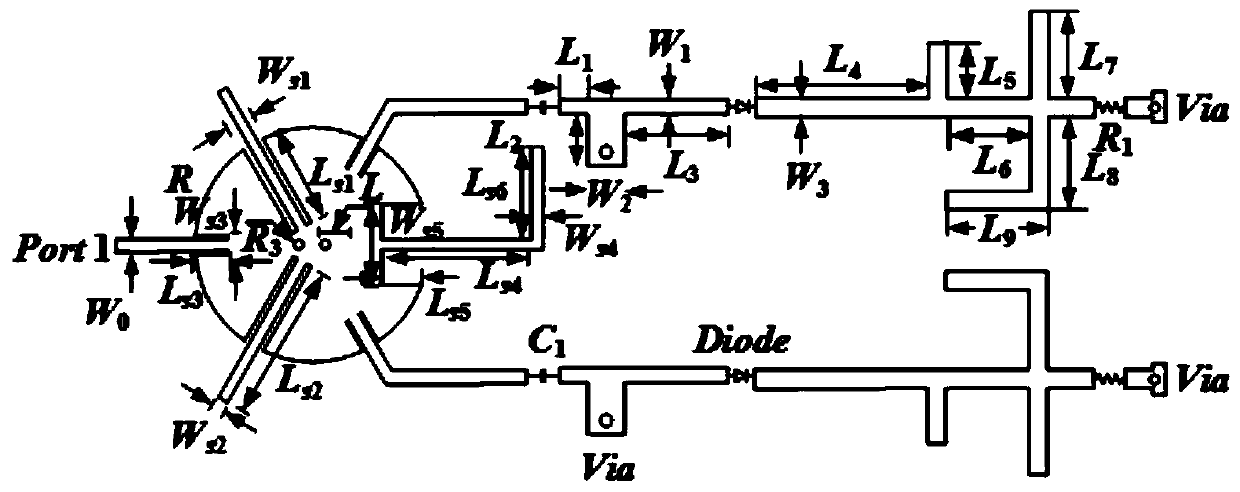
[0041] Such as figure 1 As shown, the rectification circuit includes a power divider with bandpass characteristics and two sub-rectification circuits connected with the power divider, wherein the sub-rectification circuits include a matching circuit, a rectifier diode, a DC filter and an impedance load, and the two sub-rectification circuits of the matching circuit The terminals are respectively connected to the power divider and the anode of the rectifier diode, the cathode of the rectifier diode is connected to the DC filter, and the DC filter is connected to the impedance load.

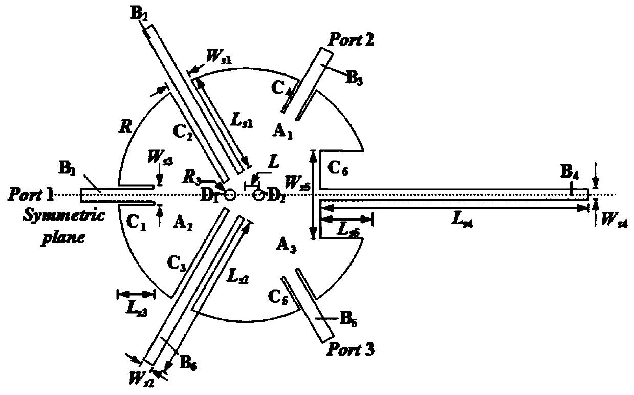
[0042] Among them, such as figure 2As shown, the power splitter includes a circular patch, impedance matching line B2, impedance matching line B4, impedance matching line B6, port line B1, port line B3 and port line B5, the radius of the circular patch is R, and the circular Slot C2, slot C3, slot C6, slot C1, slot C4 and slot C5 are respectively opened on the patch along its radial direction, be...

Embodiment 2

[0049] In this embodiment, on the basis of the rectifier circuit provided in Embodiment 1, a specific simulation experiment is carried out, and the parameters used in the experiment are as follows:

[0050] Power splitter working parameters at 2.45GHz: W 0 = 1.38, R = 12.9, R 3 = 0.5, W s1 = 2.4, L s1 =11.2, W s2 = 1.7, L s2 = 17.7, W s3 = 2.2, L s3 = 3.7, W s4 = 1.1, L s4 = 15.6, L s6 =10.5, W s5 = 8.8, L s5 = 5.1, L = 1.5.

[0051] Working parameters of sub rectifier circuit at 2.45GHz: C 1 =5pF, R 1 =1200Ω, L 1 = 3, L 2 = 5.9, L 3 =11.6, L 4 = 19, L 5 = 5.8, L 6 = 9, L 7 = 9, L 8 = 10.1, L 9 = 8.8, W 1 = 1.6, W 2 =3.9, W 3 = 2.2.

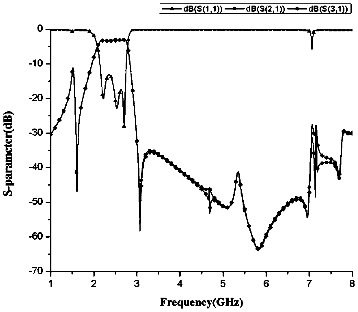
[0052] The specific experimental results are as Figure 3~7 as shown,

[0053] Such as image 3 As shown, the rectifier circuit can suppress the third harmonic at 2.45GHz.

[0054] Such as Figure 4 As shown, the center frequency of the rectifier circuit with ba...


PUM


Abstract

The invention relates to a rectifier circuit with bandpass characteristics and a wide input power range, which comprises a power divider with the bandpass characteristics and two sub rectifier circuits connected with the power divider, wherein each sub rectifier circuit comprises a matching circuit, a rectifier diode, a DC filter and an impedance load; two ends of the matching circuit are connected with the power divider and the anode of the rectifier diode; the cathode of the rectifier diode is connected with the DC filter; and the DC filter is connected with the impedance load.

Description

technical field [0001] The invention relates to the field of microwave energy transmission systems, in particular to a rectifier circuit with band-pass characteristics and wide input power range. Background technique [0002] With the demand for new energy and the rapid development of wireless technology, the application fields of wireless energy transmission are becoming more and more extensive. Wireless energy transmission refers to a process in which energy is transmitted from an energy source to an electrical load. This process gets rid of the traditional wire transmission and is realized through free space. The main mechanism of the wireless energy transmission system is to convert DC energy into microwave energy for energy transmission through the transmitting antenna. After receiving the energy, the receiving antenna rectifies it through a rectification circuit, and then reconverts the received RF energy into DC power that can be used by the device. In wireless energ...

Claims


Application Information

Patent Timeline
Patent Type & Authority Patents(China)
IPC IPC(8): H02M7/40
CPCH02M7/40
Inventor 郑少勇柳文举李元新向炳洁
Owner SYSU CMU SHUNDE INT JOINT RES INST
Why Eureka
Try Eureka