Railway power source cable leakage current on-line detection device and method

A technology of railway power supply and detection device, applied in the field of detection, can solve problems such as easy connection of wrong wires, faults, easy burning of multimeter test leads, etc., and achieve the effect of improving safety

Pending Publication Date: 2018-11-16
MIANYANG WEIBO ELECTRONICS
View PDF0 Cites 3 Cited by
  • Summary
  • Abstract
  • Description
  • Claims
  • Application Information

AI Technical Summary

Problems solved by technology

[0007] The technical problem to be solved by the present invention is that the power supply of the signal cable needs to be cut off first to ensure personal safety and signal line safety during the detection of the existing railway power supply, and then the power supply of the signal cable should be cut off manually, and then the cable to be tested should be tested by powering on after wiring. The test speed is slow, the efficiency is low, and it is easy to connect the wrong wire. When the current is large, it is easy to burn the multimeter pen, and it is easy to spark when the contact is not good, resulting in failure or inaccurate measurement. The purpose is to provide a railway power cable leakage current online Detection device and method to solve the above problems

Method used


Image

  • Railway power source cable leakage current on-line detection device and method
  • Railway power source cable leakage current on-line detection device and method
  • Railway power source cable leakage current on-line detection device and method

Examples


Embodiment 1

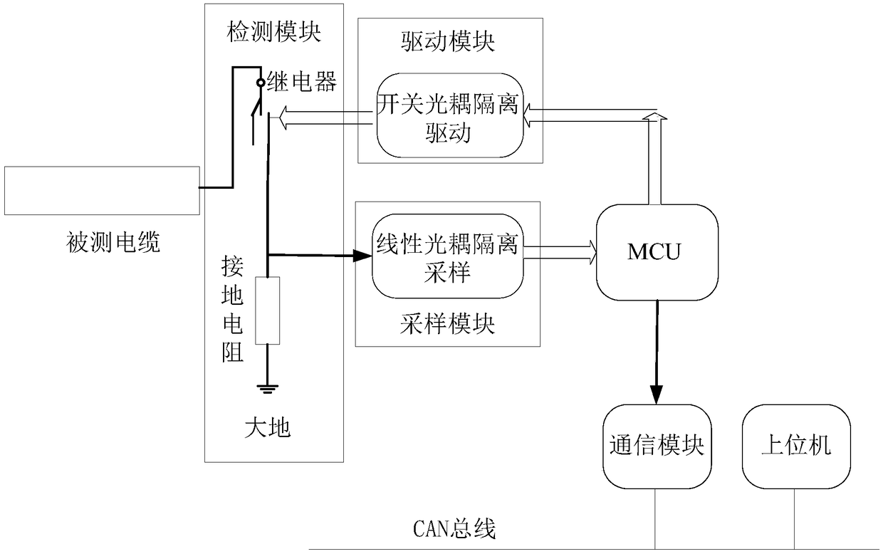
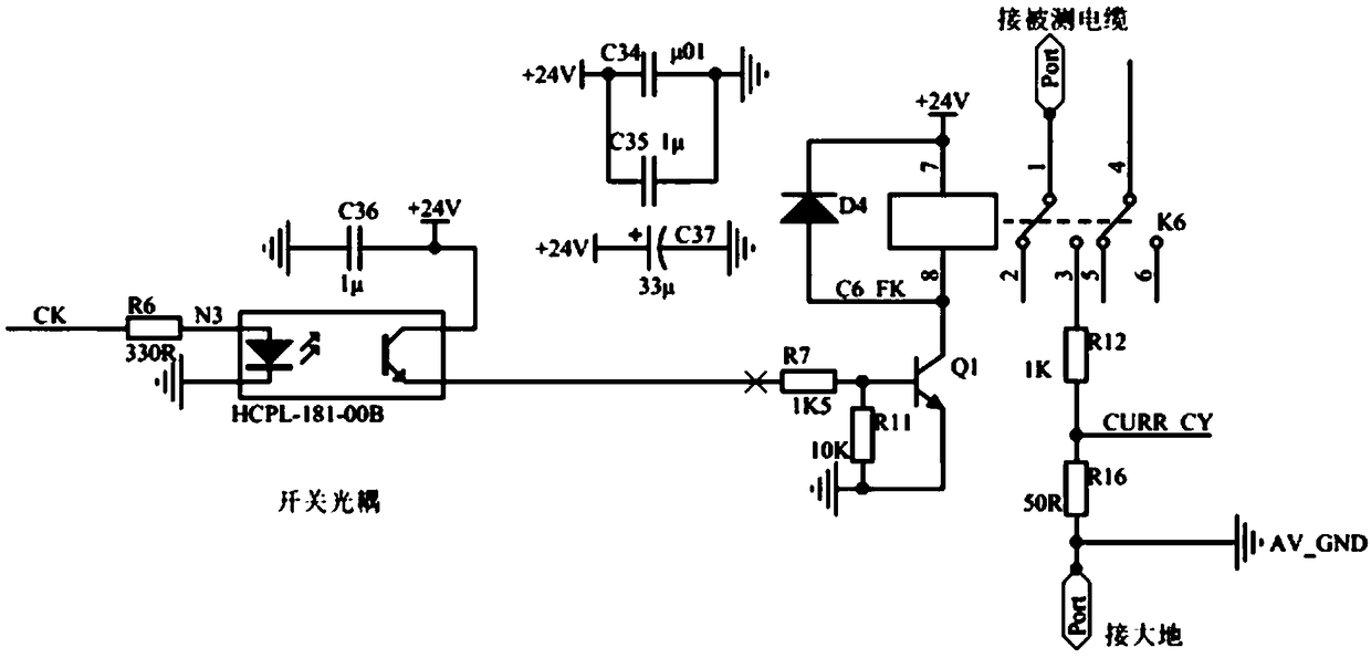
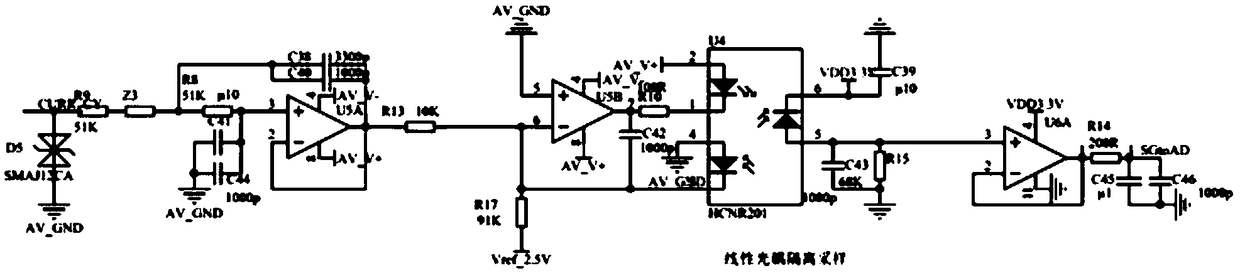
[0040] Such as figure 1 As shown, an on-line detection device and method for railway power cable leakage current of the present invention includes a detection module, a drive module and a sampling module; the detection module includes a series connected relay and a grounding resistor; The grounding resistance is grounded at one end far away from the relay; the drive module is driven by a switch optocoupler isolation, and the drive module is connected to the detection module and controls the opening and closing of the relay; the sampling module adopts linear optocoupler isolation sampling, and the sampling module Connect the detection module and sample the signal in the detection module.

[0041] When this embodiment is implemented, when the insulation of the power cable is aging, there will be poor insulation to the ground. At this time, the power cable will form a leakage current through the grounding resistance, and the leakage current will form a voltage on the grounding re...

Embodiment 2

[0043] In this embodiment, on the basis of Embodiment 1, the end of the relay away from the grounding resistance is connected between the shielding network and the core wire of the cable under test.

[0044] During the implementation of this embodiment, different from the detection of the railway signal cable, the inventor found that the relay cannot be connected to the core wire due to the high power supply of the railway power cable, so the method of connecting the end of the relay away from the grounding resistance to the cable under test is adopted. Between the shielding net and the core wire, so as to achieve the purpose of insulation detection.

[0045] Although there is an online detection technology for railway signal cables in the prior art, the difference between the two is very obvious:

[0046] First of all, the voltage of the railway power cable is very high, which cannot be adapted by conventional isolation and detection methods. The maximum voltage of the railwa...

Embodiment 3

[0049] In this embodiment, on the basis of Embodiment 1, the present invention further includes an MCU; the MCU is connected to the driving module and the sampling module.

[0050] During the implementation of this embodiment, the MCU is used to control the driving module and the sampling module, thereby further strengthening the safety effect of the present invention. It should be pointed out that the control of the driving module and the sampling module through the MCU belongs to the prior art. For the driving module The control of the device is mainly carried out in the form of a strobe signal. The so-called strobe means that when the strobe pin receives a positive (or negative) signal from the upper stage, the device starts to work. This is an existing technology; Yes, the process control of sampling module collection is also an existing technology.


PUM


Abstract

The invention discloses a railway power source cable leakage current on-line detection device. The device includes a detection module, a driving module and a sampling module; the detection module comprises a relay and a grounding resistor which are connected in series with each other; one end of the relay, which is far away from the grounding resistor, is connected with a cable under test; one endof the grounding resistor, which is far away from the relay, is grounded; the driving module adopts switching optocoupler-based isolation driving; the driving module is connected with the detection module and controls the switching on and switching off of the relay; and the sampling module performs linear optocoupler-based isolation sampling. The invention also discloses a railway power source cable leakage current on-line detection method. With the railway power source cable leakage current on-line detection device and method of the invention adopted, the online safety detection of the ground leakage current of a railway power source cable is realized. The device and the method of the invention have the advantages of high detection precision, strong anti-interference capacity, high safety and high reliability. With the railway power source cable leakage current on-line detection device and method of the invention adopted, electricians can grasp the ground leakage current of the powersource cable online in real time, and discover hidden dangers in time, and therefore, the operation of a railway will not be affected.

Description

technical field [0001] The invention relates to the technical field of detection, in particular to an on-line detection device and method for railway power cable leakage current. Background technique [0002] The railway signal room and mechanical room are equipped with a large number of equipment signal equipment, and also use a variety of power supplies, including AC power supply, DC power supply, and track signal power supply. The laying distance of these cables is usually 1 to 3km, and leakage current is likely to occur anywhere the insulation performance decreases, and leakage current not only endangers personal safety, may cause equipment to catch fire, affect the normal operation of equipment, and may even cause equipment to fail to operate and safety accidents in severe cases . [0003] Therefore, the railway site needs a means and method that can detect the ground leakage current of the power cable, and ensure safety during detection without seriously affecting the...

Claims


Application Information

Patent Timeline
Patent Type & Authority Applications(China)
IPC IPC(8): G01R31/02
CPCG01R31/50G01R31/58
Inventor 刘胜涛
Owner MIANYANG WEIBO ELECTRONICS
Why Eureka
Try Eureka