An anti-theft trailer arm
A technology for trailers and adjustable arms, which is applied to vehicle parts, traction connectors, transportation and packaging, etc. It can solve the problems of unsolved problems such as the height-adjustable function of straightening, and achieve the effects of reducing anti-theft costs, simplifying anti-theft operations, and streamlining anti-theft devices
- Summary
- Abstract
- Description
- Claims
- Application Information
AI Technical Summary
Problems solved by technology
Method used
Image
Examples
Embodiment 1
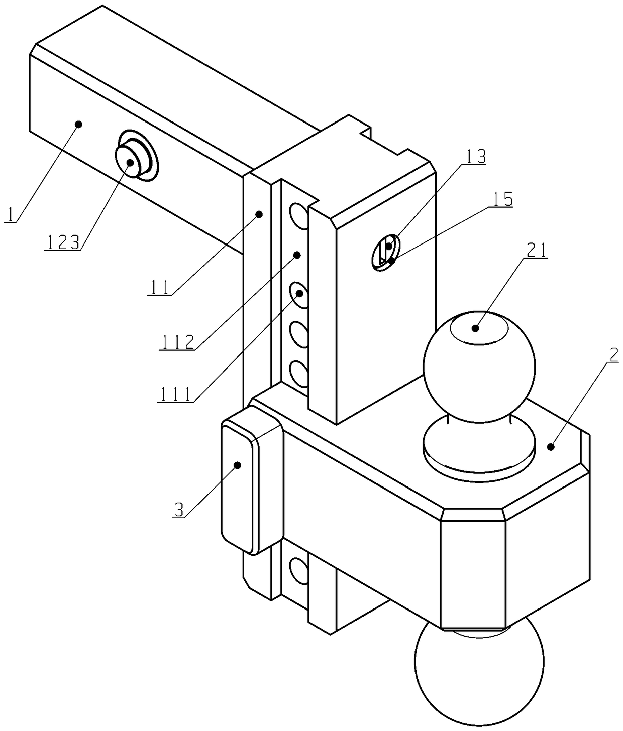
[0033] An anti-theft trailer arm, comprising: an L-shaped main arm 1, which is used to be fixedly connected with the quick-plug square opening of the chassis of a motor vehicle; The appliance is connected with the towed motor vehicle; the locking pin 3 is used for locating and fixing the relative position of the adjusting arm 2 and the main arm 1 .
[0034] The height adjustment positioning hole 111 of the vertical arm 11 is used for height adjustment and positioning of the adjustment arm 2; the lock pin 3 passes through the lock pin hole 221 on the bayonet 21 of the adjustment arm 2, is inserted into the positioning hole 111, and is fixedly connected to the adjustment arm 2 and the vertical arm 11 and provide the load supporting force in the vertical direction for the adjusting arm 2.
Embodiment 2
[0036] The front end 125 of the lock crankshaft 12 in the inner cavity of the horizontal arm of the main arm 1 is connected with the lock cylinder 13 through the crankshaft connecting shaft 121 and is driven by the rotation of the lock cylinder 13 . The left part 123 and the right part 124 of the separated main deadbolt on both sides are interspersed and connected vertically and radially to the locked crankshaft 12 at the rear end 126 of the locked crankshaft 12, and the locked rack 122 passes through the rack connecting rod 127 It is hingedly connected with the lock crankshaft 12 at the front end 125 of the lock crankshaft. When the main arm lock cylinder 13 rotates axially, the crankshaft connecting shaft 121 drives the lock crankshaft 12 to rotate, so that the rear end 126 of the lock crankshaft drives the separated main bolts 123 and 124 on both sides to perform opposite axial reciprocating motions. The maximum value and the minimum value of the displacements of the separa...
Embodiment 3
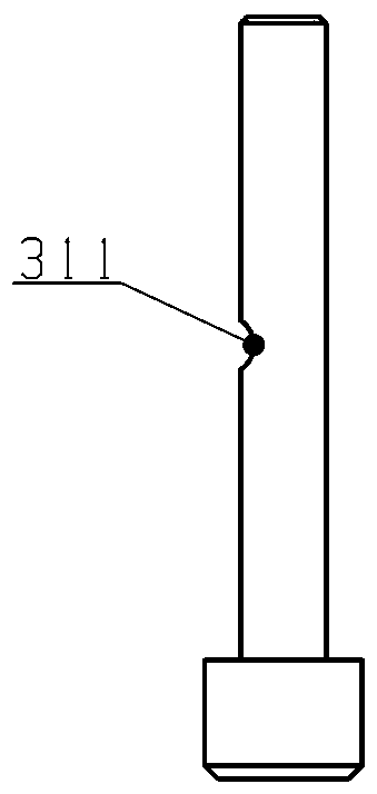
[0038] When the main arm lock core 13 is in the locked state, the positions of the components are as follows: Figure 6 , figure 2 Shown: the detachable main bolts 123, 124 are stretched out, and are firmly connected with the quick-plug square opening of the automobile. The front end 125 of the lock crankshaft is now at the 6 o'clock position on the end face of the lock crankshaft 12, the lock rack 122 is at the lowest end of the stroke, the rack tooth top 1222 enters the positioning hole 111, and just meshes with the latch lock notch 311 of the lock latch 3, It forms a physical intersection with the deadbolt pin rod 31, at this time the deadbolt 3 cannot be drawn out, and further, the adjusting arm 2 cannot be moved or taken out.
[0039] Turn the lock cylinder key 180 degrees clockwise, the crankshaft 12 of the main arm lock driven by the lock cylinder 13 drives the left part 123 of the separated main deadbolt on both sides, and the right part 124 of the separated main dea...
PUM
 Abstract
Description
Claims
Application Information
 - R&D
- Intellectual Property
- Life Sciences
- Materials
- Tech Scout
- Unparalleled Data Quality
- Higher Quality Content
- 60% Fewer Hallucinations
Browse by: Latest US Patents, China's latest patents, Technical Efficacy Thesaurus, Application Domain, Technology Topic, Popular Technical Reports.
© 2025 PatSnap. All rights reserved.Legal|Privacy policy|Modern Slavery Act Transparency Statement|Sitemap|About US| Contact US: help@patsnap.com


