Electronic device and backlight control method and backlight control device thereof

An electronic device and backlight control technology, applied in the direction of instruments, static indicators, etc., can solve problems such as poor energy saving effect, and achieve the effect of reducing power consumption and realizing energy saving effect.

Inactive Publication Date: 2017-01-18
GREE ELECTRIC APPLIANCES INC
View PDF6 Cites 5 Cited by
  • Summary
  • Abstract
  • Description
  • Claims
  • Application Information

AI Technical Summary

Problems solved by technology

[0004] The embodiment of the present invention aims to solve the problem that the energy-saving effect of the existing electronic device backlight control method is poor.

Method used


Image

  • Electronic device and backlight control method and backlight control device thereof
  • Electronic device and backlight control method and backlight control device thereof
  • Electronic device and backlight control method and backlight control device thereof

Examples


Embodiment Construction

[0027] The technical solutions of the present invention will be clearly and completely described below in conjunction with the accompanying drawings. Apparently, the described embodiments are some of the embodiments of the present invention, but not all of them. Based on the embodiments of the present invention, all other embodiments obtained by persons of ordinary skill in the art without making creative efforts belong to the protection scope of the present invention.

[0028] In addition, the technical features involved in the different embodiments of the present invention described below may be combined with each other as long as there is no conflict with each other.

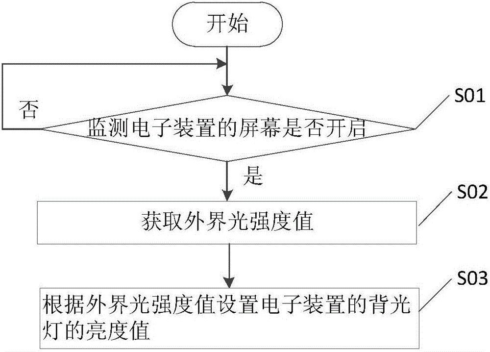
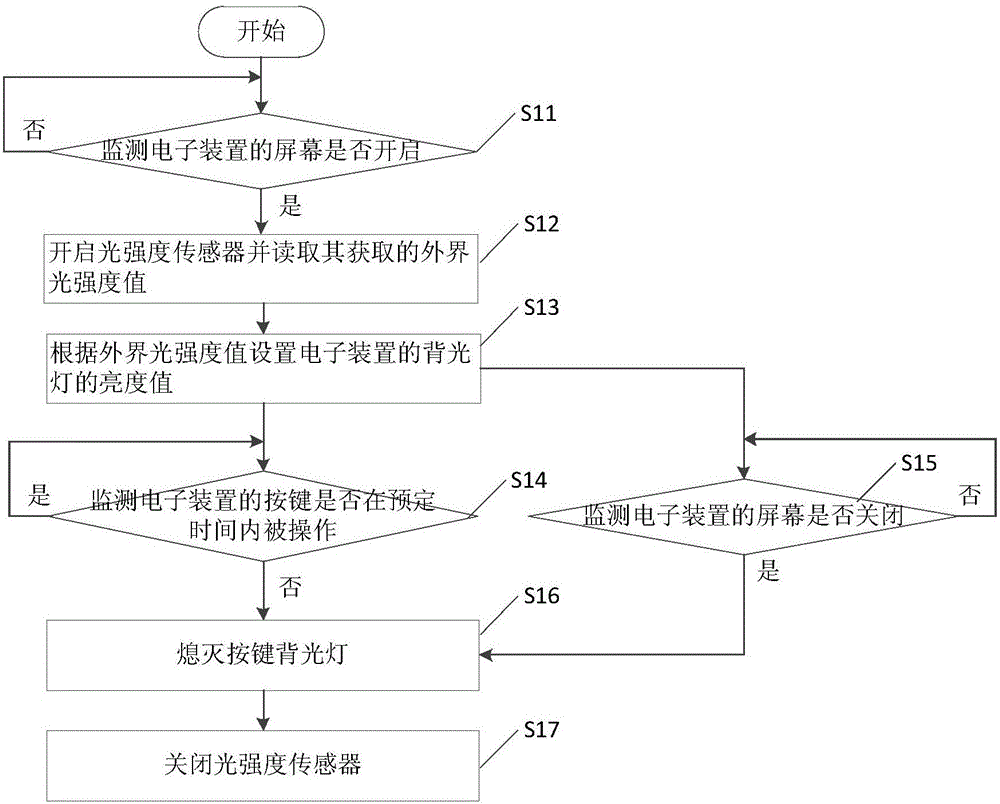
[0029] The embodiment of the present invention provides a method for controlling the backlight of an electronic device, which can be used to control electronic devices with screens and backlights such as smart phones and tablet computers. The light emitting element of the indicator light. Such as figure 1 A...


PUM


Abstract

The invention provides an electronic device and a backlight control method and a backlight control device thereof. The method comprises the steps of monitoring whether the screen of an electronic device is turned on, acquiring the intensity value of outside light when the screen of the electronic device is turned on, and setting the brightness value of the backlight of the electronic device according to the intensity value of outside light.

Description

technical field [0001] The invention relates to the field of terminal control, in particular to an electronic device and a backlight control method and device thereof. Background technique [0002] At present, the power consumption of smart terminals such as mobile phones and tablet computers has become a bottleneck for function improvement. With the continuous enrichment and enhancement of functions, the power consumption of smart terminals has also increased. However, in recent years, the storage capacity of batteries has not been substantially improved, so that the battery life of smart terminals is insufficient. Therefore, the low power consumption of smart terminals The importance of power consumption technology is becoming more and more prominent. [0003] Existing smart terminals can receive user operations through a touch screen, and most smart terminals are also equipped with physical buttons. In order to achieve the purpose of aesthetics or easy identification, s...

Claims


Application Information

Patent Timeline
Patent Type & Authority Applications(China)
IPC IPC(8): G09G3/34
CPCG09G3/3406G09G2320/062
Inventor 田浩雨
Owner GREE ELECTRIC APPLIANCES INC
Why Eureka
Try Eureka