Humidification equipment for spinning

A technology for humidifying equipment and water tanks, which is applied in the fields of textile processing machine accessories, textiles and papermaking, textile materials, etc. It can solve the problems of easy adsorption and deformation of fabrics, property loss, and insufficient device treatment, etc., and achieve low humidification efficiency. , increase the operating area, increase the effect of efficiency

Inactive Publication Date: 2017-02-15
ZHEJIANG KEYI TEXTILE
View PDF1 Cites 0 Cited by
  • Summary
  • Abstract
  • Description
  • Claims
  • Application Information

AI Technical Summary

Problems solved by technology

[0002] In the textile industry, a large number of textile materials and textile products are piled up in a concentrated manner. When the weather is dry in autumn and winter, the raw materials are easy to generate static electricity due to drying, causing the fabric to absorb and deform easily. In the clothing industry with increasingly fierce competition pressure, it is difficult to be effective. Occupying the market, a large number of clothes are piled up, and it is easy to catch fire in dry air, causing greater property damage;
[0003] At present, in the textile industry, humidifiers are used to humidify the fabrics to ensure the humidity of the clothes and achieve the purpose of smoothness and safety. The existing humidifiers intelligently place the water tank at a designated position, and drag the water pipes to humidify different positions. This is very convenient. To a large extent, the humidification of clothes is limited. For example, the Chinese patent with the patent number of CN 105274660 A can only be humidified at a designated position. In addition, the existing humidification equipment only has a fixed humidification speed when humidifying, and the applicability is not high. , the existing devices are not good enough for the occasions where a large amount of humidification and a small amount of humidification are required

Method used


Image

  • Humidification equipment for spinning

Examples


Embodiment

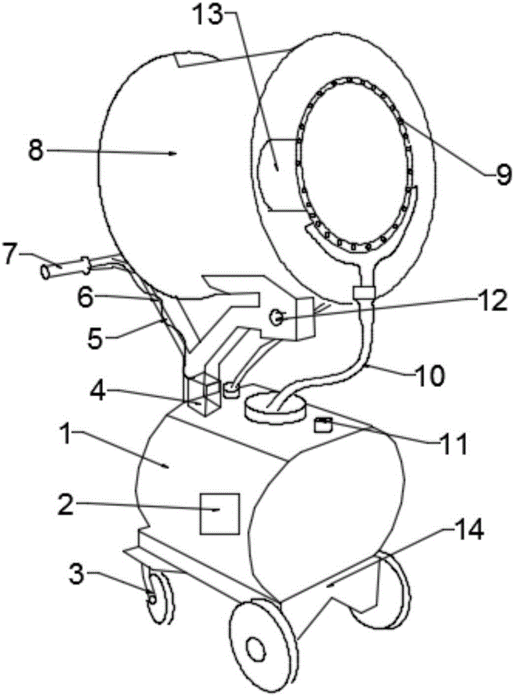
[0016] see figure 1 , the present invention provides a technical solution: a humidification device for textiles, including a water tank 1, a water pump 2 is installed inside the water tank 1, an electric control box 4 is installed above the water tank 1, and beside the electric control box 4 A water pipe 10 is installed, and a water inlet 11 is installed next to the water pipe 10. A support frame 12 is installed above the electric control box 4. The humidification cylinder 8 and the support frame 12 are engaged by gears, and the meshing method is adopted, so that The humidifying cylinder 8 can freely rotate the angle of humidification to facilitate the rotation angle. The humidifying cylinder 8 is installed on the support frame 12, and the atomizing nozzle 9 is installed inside the humidifying cylinder 8, and the atomizing nozzle 9 is installed in a circular shape. And atomizing nozzle 9 is all connected with water pipe 10, adopts circular atomizing nozzle 9, the area of ​​hum...


PUM


Abstract

The invention discloses a piece of humidification equipment for spinning. The equipment comprises a water tank, wherein a water pump is installed in the water tank, an electric control box is installed on the water tank, a water pipe is installed beside the electric control box, a water adding hole is installed beside the water pipe, a supporting frame is installed on the electric control box, a humidification cylinder is installed on the supporting frame, an atomization sprayer is installed in the humidification cylinder, and fan blades are installed behind the atomization sprayer; and a base is installed on the bottom of the water tank, universal wheels are installed on the base, a handle is installed on the base, a speed-regulation knob is installed on the handle, a cable is disposed between the speed-regulation knob and the electric control box, and the speed-regulation knob and the electric control box are connected together by the cable. The device is characterized in that hand-push humidification design is adopted, so that the humidification equipment can be easily pushed to a designated position; speed regulation design is adopted, so that different spinning materials can be humidified; in addition, the fan blades are installed behind the atomization sprayer, so that humidification efficiency is increased; and the device has very good application prospect.

Description

technical field [0001] The invention relates to the technical field of reaction devices, in particular to a humidifying device for textiles. Background technique [0002] In the textile industry, a large number of textile materials and textile products are piled up in a concentrated manner. When the weather is dry in autumn and winter, the raw materials are easy to generate static electricity due to drying, causing the fabric to absorb and deform easily. In the clothing industry with increasingly fierce competition pressure, it is difficult to be effective. Occupying the market, a large number of clothes are piled up, and it is easy to catch fire in dry air, causing greater property damage; [0003] At present, in the textile industry, humidifiers are used to humidify the fabrics to ensure the humidity of the clothes and achieve the purpose of smoothness and safety. The existing humidifiers intelligently place the water tank at a designated position, and drag the water pipes...

Claims


Application Information

Patent Timeline
Patent Type & Authority Applications(China)
IPC IPC(8): D06B1/02D06B23/00
CPCD06B1/02D06B23/00
Inventor 沈建明蘧孝玲
Owner ZHEJIANG KEYI TEXTILE
Why Eureka
Try Eureka