
Common-mode choke coil and manufacturing method therefor

A technology of common mode choke coil and manufacturing method, applied in the direction of inductor/transformer/magnet manufacturing, transformer/inductor coil/winding/connection, inductor, etc. suppress the effect

Active Publication Date: 2017-02-15
MURATA MFG CO LTD
View PDF7 Cites 16 Cited by
  • Summary
  • Abstract
  • Description
  • Claims
  • Application Information

AI Technical Summary

Problems solved by technology

As a result, in existing common mode choke coils, there is a problem of generating mode conversion

Method used


Image

  • Common-mode choke coil and manufacturing method therefor
  • Common-mode choke coil and manufacturing method therefor
  • Common-mode choke coil and manufacturing method therefor

Examples


Embodiment Construction

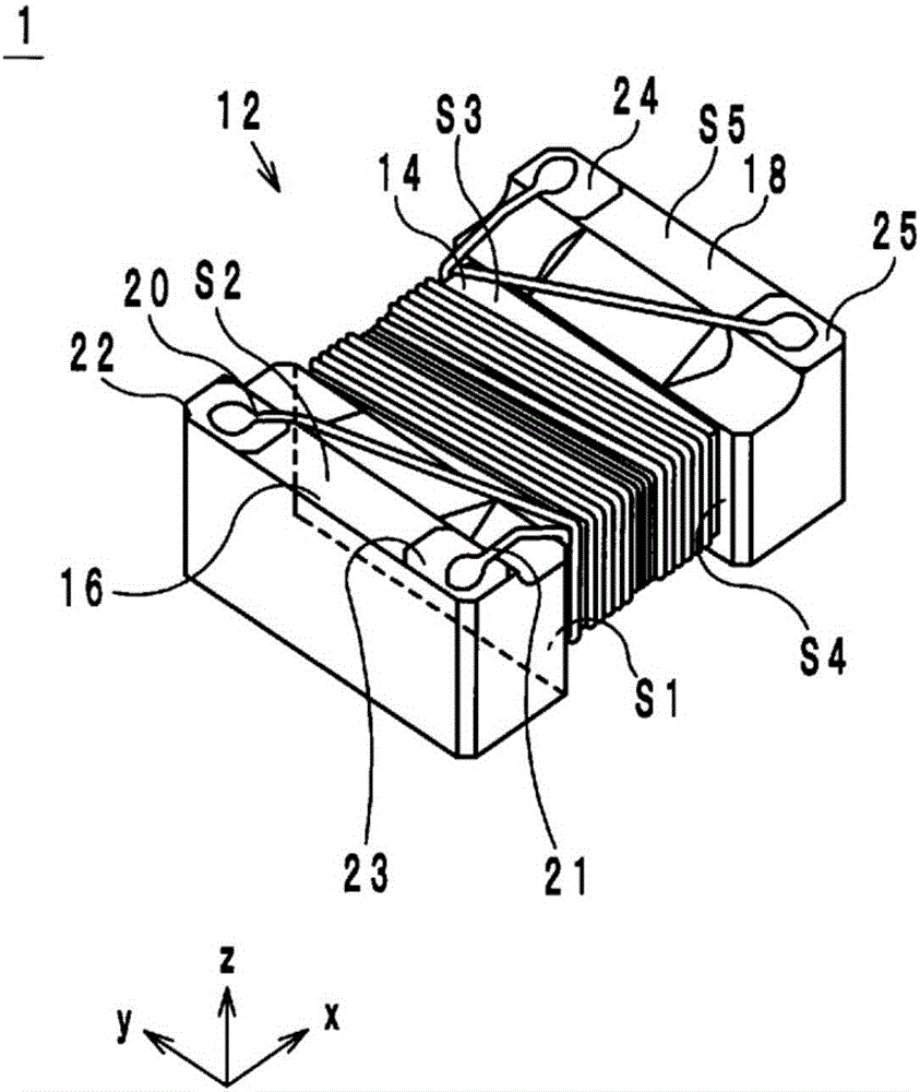
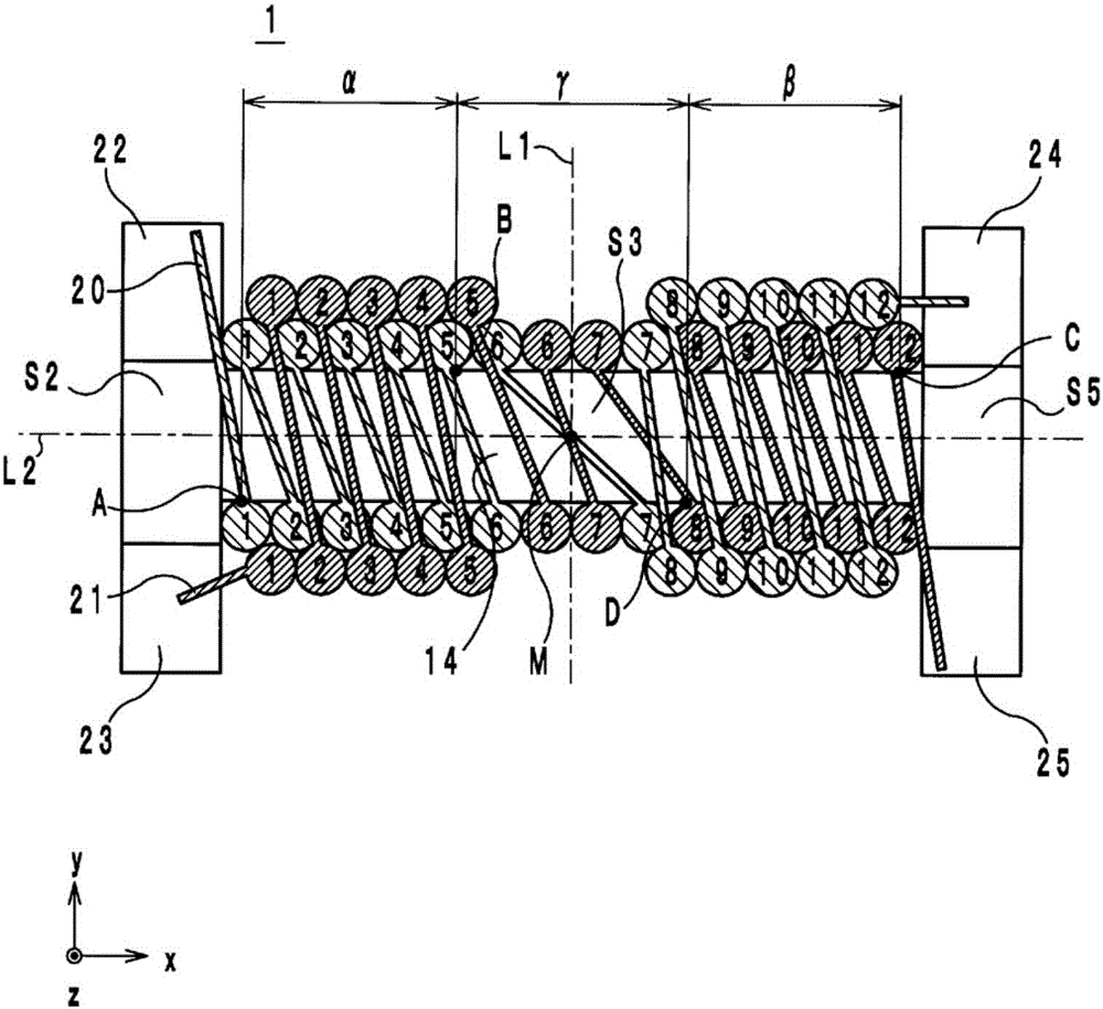
[0051] (For the structure of the common mode choke coil, refer to figure 1 as well as figure 2 )

[0052]A common mode choke coil 1 according to an embodiment will be described with reference to the drawings. Hereinafter, the direction in which the central axis of the winding core portion 14 extends is defined as the x-axis direction. In addition, when viewing the x-axis direction, the direction along the long side of the flange portion 16 is defined as the y-axis direction, and the direction along the short side of the flange portion 16 is defined as the z-axis direction. In addition, the x-axis, y-axis, and z-axis are orthogonal to each other.

[0053] Such as figure 1 As shown, the common mode choke coil 1 includes an iron core 12 , winding wires 20 and 21 , and external electrodes 22 to 25 . Such as figure 2 As shown, the common mode choke coil 1 is roughly divided into the starting line side area α (first area) as the starting winding end of the winding wires 20...


PUM


Abstract

The purpose of this invention is to provide a common-mode choke coil that inhibits mode conversion and a method for manufacturing said common-mode choke coil. Said common-mode choke coil (1) comprises a core, which has a winding-core section (14), and windings (20 and 21). A wire-start region (alpha) extends from one end (A) where one winding (20) contacts the winding-core section (14) to a given position (B), and a wire-end region (beta) extends from the other end (C) where the other winding (21) contacts the winding-core section (14) to another given position (D). With respect to an x-axis, the turns of the former winding (20) are each located on the negative side of the corresponding turn of the latter winding (21) in the wire-start region (alpha) and are wound around the winding-core section (14) so as to sandwich the turns of the latter winding (21) in the wire-end region (beta), whereas the turns of the latter winding (21) are each located on the positive side of the corresponding turn of the former winding (20) in the wire-end region (beta) and are wound around the winding-core section (14) so as to sandwich the turns of the former winding (20) in the wire-start region (alpha). The number of turns of the former winding (20) and the number of turns of the latter winding (21) are equal, as are the number of turns of the former winding (20) that are wound so as to contact the winding-core section (14) and the number of turns of the latter winding (21) that are wound so as to contact the winding-core section (14).

Description

technical field [0001] The present invention relates to a common mode choke coil and a manufacturing method thereof. Background technique [0002] As a conventional common mode choke coil, the common mode choke coil described in Patent Document 1 is known. In such common mode choke coils (hereinafter referred to as conventional common mode choke coils), such as Figure 23 As shown in , two conductive wires are wound in parallel on a winding core extending in the x-axis direction. In addition, the conventional common mode choke coil has a first region where one lead wire is wound around the winding core so as to sandwich the other lead wire, and a first region where one lead wire is wound so as to sandwich the other lead wire. Wound around the second area of ​​the core. This is to make the number of turns of the wires in the first region and the second region the same and to make the lengths of the two wires the same in the existing common mode choke coil, thereby suppressi...

Claims


Application Information

Patent Timeline
Patent Type & Authority Applications(China)
IPC IPC(8): H01F17/04H01F27/28H01F41/066
CPCH01F17/045H01F27/006H01F2017/0093H01F41/073H01F41/069H01F27/2823H01F27/29
Inventor 山北高之
Owner MURATA MFG CO LTD
Learn More