Bottom line detection device

A technology for detecting device and bottom thread, which is applied to bobbin winding in sewing machines, textiles and papermaking, sewing equipment, etc., can solve the problem of inconvenient replacement of bobbins, and achieve the effects of easy adjustment, smooth expansion, and prevention of seam emptiness.

Active Publication Date: 2019-08-06
KINOSHITA SEIMITSU INDS
View PDF9 Cites 0 Cited by
  • Summary
  • Abstract
  • Description
  • Claims
  • Application Information

AI Technical Summary

Problems solved by technology

[0002] In the past, the bobbin thread used in the sewing machine was installed in the sewing machine after putting the thread wound on the bobbin into the bobbin case, but due to the automation and enlargement of the sewing machine, it was necessary to go deep into the sewing machine when installing it. The depth of the table makes it very inconvenient to replace the bobbin

Method used


Image

  • Bottom line detection device
  • Bottom line detection device
  • Bottom line detection device

Examples


Embodiment Construction

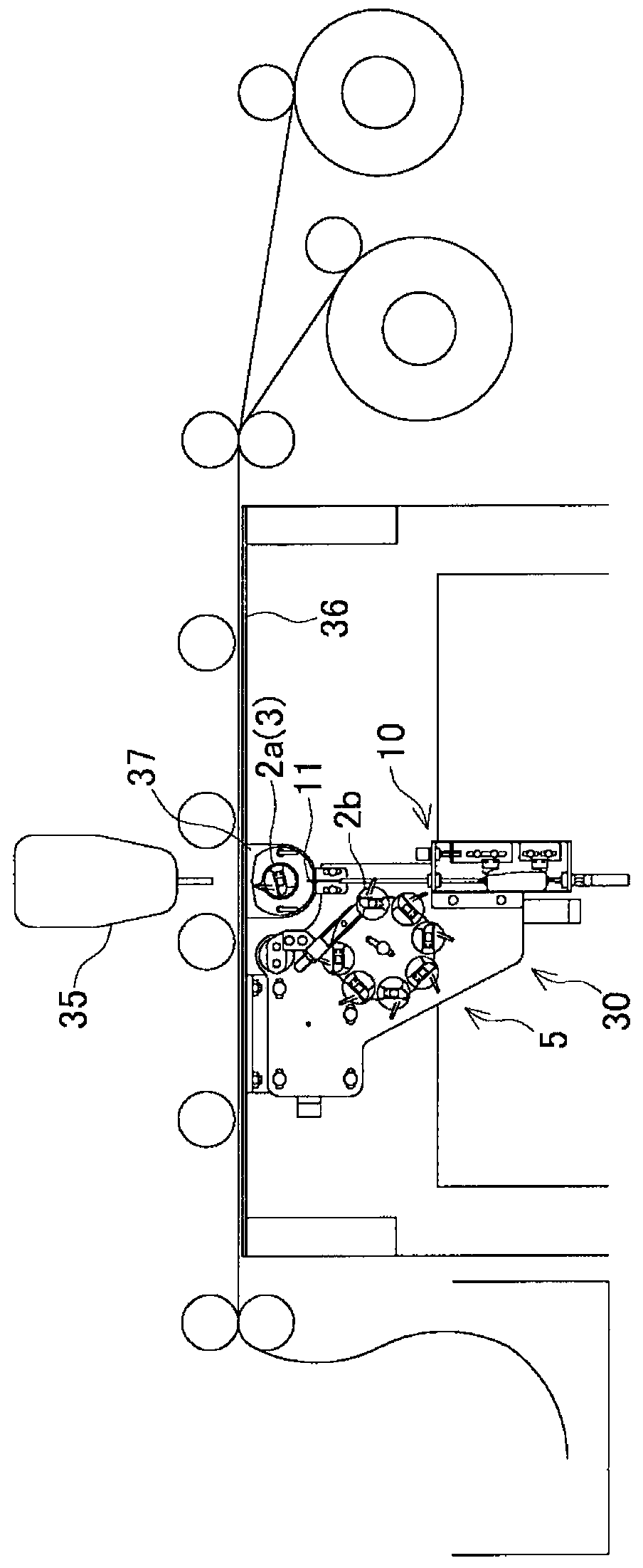
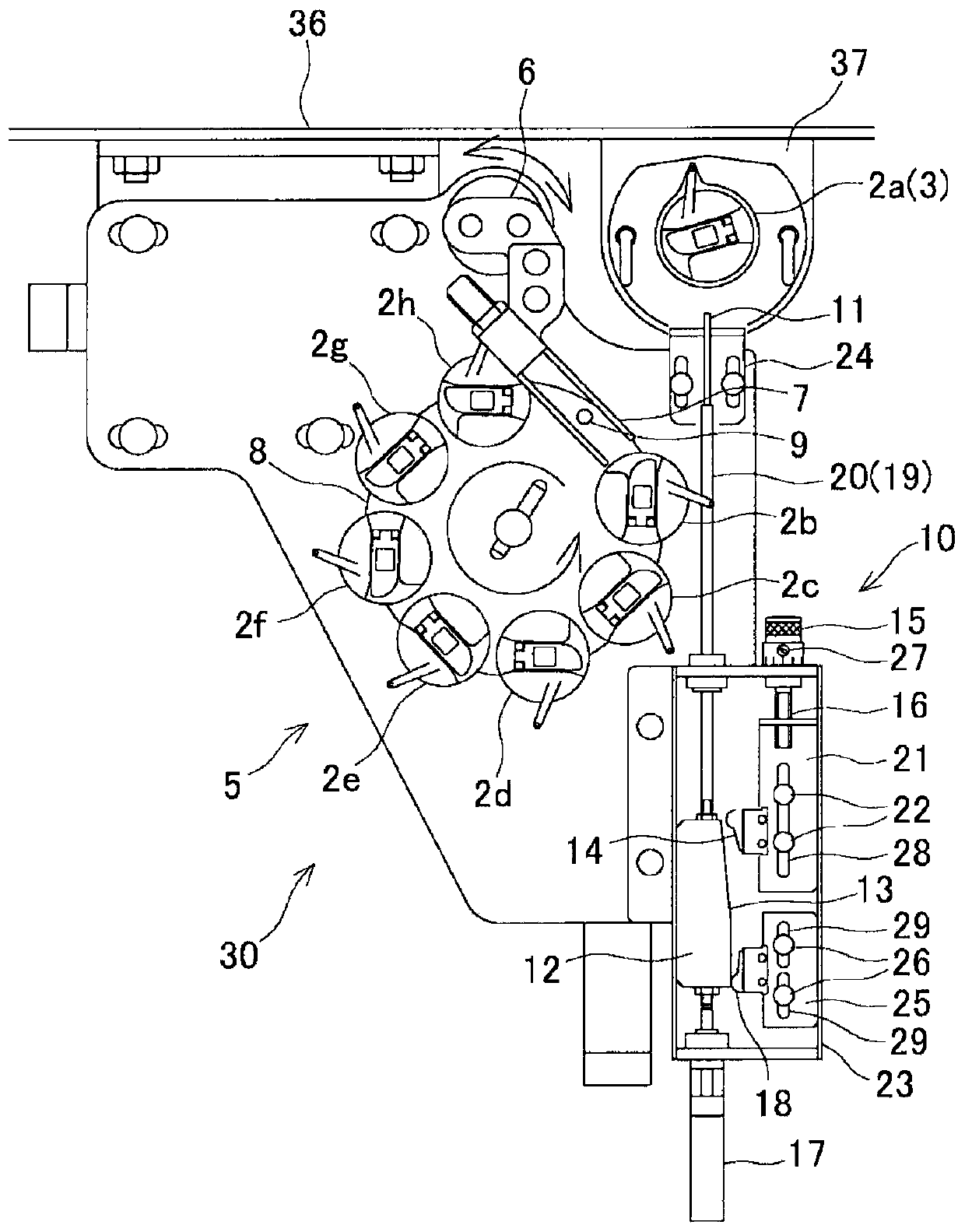
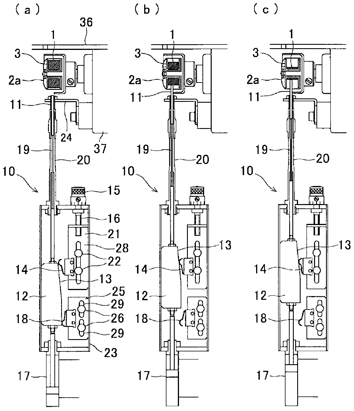
[0036] Next, an embodiment in which the bobbin thread replacing device according to the present invention performs bobbin thread replacement based on detection of the remaining amount of bobbin thread will be described in detail with reference to the drawings.

[0037] figure 1 It is an explanatory diagram showing a state where the bobbin thread changing device is installed on the sewing table. figure 2 It is an explanatory diagram showing the bobbin thread changing device. image 3 It is an explanatory diagram showing the input of the contact switch for measuring the stopper by the detection rod. Figure 4 It is an explanatory diagram showing a state in which a detection pin is extended by an air cylinder and an electromagnetic switch. Figure 5 It is an explanatory diagram showing the state where the position adjustment knob is rotated and the contact switch is slid. Figure 6 It is an explanatory diagram showing the relationship between the winding length and the windi...


PUM


Abstract

A coil thread detector (10) includes a detecting pin (11) extending from an outer periphery toward a center in a radial direction of a bobbin (3), a moving unit which moves the detecting pin (11) toward the center of the bobbin (3) ), a contact switch (14) which detects the movement of the detecting pin (11), and a position adjusting knob (15) which screws the contact switch (14) in a moving direction of the detecting pin (11) to set a position. A residual quantity of a bobbin thread (1) is detected with the bobbin thread detector (10) in order to obtain a suitable replacement time of the bobbin (3), and thus it is not necessary to pay attention to the residual quantity of the bobbin thread (1) and a sewing machine (35) is prevented from empty sewing. Setting a position of the contact switch (14) guarantees an arbitrary change in the exchange time.

Description

technical field [0001] The present invention relates to a bobbin thread detecting device for detecting bobbin thread used in a sewing machine. Background technique [0002] In the past, the bobbin thread used in the sewing machine was installed in the sewing machine after putting the thread wound on the bobbin into the bobbin case, but due to the automation and enlargement of the sewing machine, it was necessary to go deep into the sewing machine when installing it. Deep in the table, the replacement of the bobbin is very inconvenient. [0003] On the other hand, in the bobbin changing device which automatically performs the bobbin changing operation, it is not necessary to go deep into the depth of the sewing table, and the changing work is not required, so it is very convenient. [0004] [Prior Art Literature] [0005] 【Patent Literature】 [0006] [Patent Document 1] Japanese Patent Laid-Open No. 2001-218991 Contents of the invention [0007] The problem to be solved...

Claims


Application Information

Patent Timeline
Patent Type & Authority Patents(China)
IPC IPC(8): D05B59/02
CPCD05B59/02
Inventor 木下治彦杉本竜三加藤征
Owner KINOSHITA SEIMITSU INDS
Why Eureka
Try Eureka