Side sheltered solar halo photometer

A photometer and height technology, applied in the direction of measuring sunlight and using electric radiation detectors for light metering, etc., can solve the problems of increasing the vignetting of the external field of view, restricting the observation, reducing the external field of view, etc., and achieves the brightness of the sky. Precise and smooth area enlargement effect

Inactive Publication Date: 2017-02-22
SHANDONG UNIV +1
View PDF6 Cites 2 Cited by
  • Summary
  • Abstract
  • Description
  • Claims
  • Application Information

AI Technical Summary

Problems solved by technology

Its disadvantage is mainly that the diffracted light in the inner field of view and the outer field of view is very strong, which limits the observation of the inner field of view and the outer field of view. In the captured image, two bright rings are generated in the inner field of view and the outer field of view. Makes its minimum actual inner field of view only 4R ⊙ (R ⊙ is the average radius of the solar photosphere)
The halo photometer of Yunnan Astronomical Observatory has suppressed part of the diffraction of the outer field of view, but the suppression method is to reduce the aperture of the third aperture. This method will reduce the diffraction of the outer field of view, but at the same time it will make the outer field of view The vignetting increases, and even directly reduces the actual observable outer field of view

Method used


Image

  • Side sheltered solar halo photometer
  • Side sheltered solar halo photometer
  • Side sheltered solar halo photometer

Examples


Embodiment 1

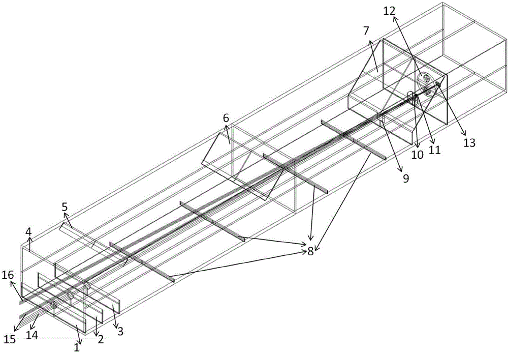
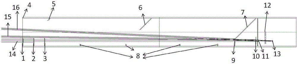
[0026] see Figure 1-Figure 3 , the invention discloses a side shielding type heliophotometer, which comprises an outer baffle, an outer window 4, an upper stray light stop, a lower stray light stop 8, and a middle stop 9 from left to right , a second attenuation film 10, an aperture stop, an objective lens 11, a filter wheel 12 and a CCD camera 13.

[0027] The photometer has a rectangular structure as a whole, and the left end of the rectangular structure is an open outer window 4, and the direct sunlight 14 enters the optical system horizontally from the left side of the outer window 2, that is, the photometer of the present invention adopts a side observation mode.

[0028] The photometer of the present invention adopts an external baffle instead of a traditional external shelter structure to reduce the intensity of diffracted light. The specific setting method of the outer baffle is as follows: the outer baffle is vertically arranged on the left part of the photometer, t...


PUM


Abstract

The invention relates to a side sheltered solar halo photometer. The photometer comprises an external baffle plate, an external window, an upper stray light eliminating diaphragm, a lower stray light eliminating diaphragm, an intermediate diaphragm, a second attenuation sheet, an aperture diaphragm, an object lens, a filter wheel and a CCD camera which are arranged from the left to the right in turn. The middle part of the external baffle plate is provided with a first attenuation sheet. The first attenuation sheet, the second attenuation sheet, the aperture diaphragm, the object lens and the CCD camera are arranged on the same axis. Direct sunlight enters an optical system to be imaged on the image plane of the CCD camera through the first attenuation sheet and the second attenuation sheet. The sky brightness is imaged on the image plane of the CCD camera through the second attenuation sheet. The relative value of the sky brightness and the solar brightness can be obtained through the brightness ratio on the image plane of the CCD camera with combination of the attenuation magnitude of the first attenuation sheet. The advantages of the side sheltered solar halo photometer are that the diffraction light intensity of the internal view field can be greatly reduced, the observable range of the internal view field can be enhanced, the sky brightness is observed from the side plane and the sky brightness of the solar range of the radial view field can be increased.

Description

technical field [0001] The invention relates to a halo photometer measuring device, in particular to a side shielding heliophotometer. Background technique [0002] The halophotometer is mainly used for the site selection of the coronagraph, and determines whether it meets the requirements of the coronagraph observation by measuring the brightness scattered by the sky. At present, there are two main types of halo photometers used internationally, one is the Evans Sky Photometer (ESP) invented by John W. Evans in 1948, and the other is the SkyBrightness Monitor (SBM) placed by Haosheng Lin et al. in Hawaii in 2004. . The halo photometer manufactured by the Yunnan Astronomical Observatory of the Chinese Academy of Sciences in 2011 is modeled on a halo photometer manufactured by SBM, but with some improvements and the use of a more advanced CCD, its time resolution is greatly improved. ESP and SBM are placed in multiple solar observatories for long-term halo photometry, and t...

Claims


Application Information

Patent Timeline
Patent Type & Authority Applications(China)
IPC IPC(8): G01J1/42
CPCG01J1/42G01J2001/4266
Inventor 孙明哲张红鑫夏利东刘维新卜和阳
Owner SHANDONG UNIV
Why Eureka
Try Eureka