A kind of oled pixel circuit and its driving method, display device

A technology of pixel circuit and driving method, which is applied in the field of display, and can solve the problems of foreign matter in the film layer, voltage increase, sub-pixel voltage increase, etc.

Active Publication Date: 2019-06-25
BOE TECH GRP CO LTD
View PDF9 Cites 0 Cited by
  • Summary
  • Abstract
  • Description
  • Claims
  • Application Information

AI Technical Summary

Problems solved by technology

[0005] However, since the film layers between the anode and cathode of the OLED are relatively thin, and there are foreign objects in the film layer, or the process of digging holes and climbing slopes is not well controlled, the film layer will be further thinned, making the anode and cathode of the OLED A short circuit occurs due to a small resistance between them, so that the voltage of the V2 terminal connected to the cathode increases
The V2 terminal between each sub-pixel is conductive, so the voltage of the V2 terminal of the short-circuited sub-pixel increases, which easily causes the voltage of the V2 terminal of its surrounding sub-pixels to also increase, thereby affecting the OLED cathode and anode in the surrounding sub-pixels. The pressure difference between them will affect the display of surrounding sub-pixels

Method used


Image

  • A kind of oled pixel circuit and its driving method, display device
  • A kind of oled pixel circuit and its driving method, display device
  • A kind of oled pixel circuit and its driving method, display device

Examples


Embodiment 1

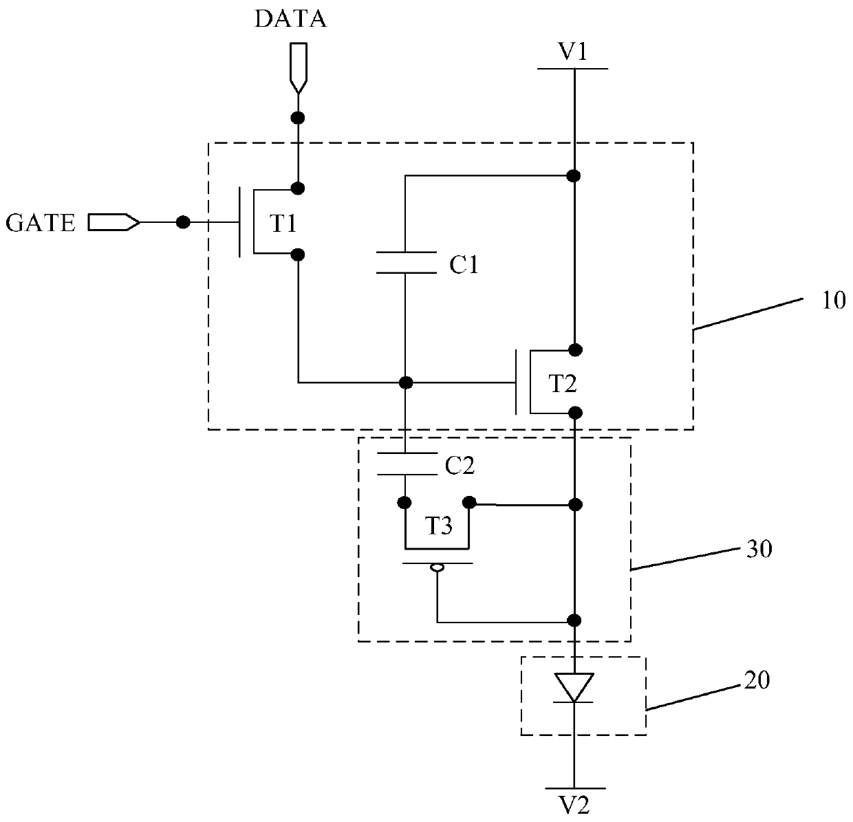
[0039] Embodiment 1 provides an OLED pixel circuit, such as image 3 As shown, the driving module 10 includes a first transistor T1, a first capacitor C1 and a second transistor T2.

[0040] The gate of the first transistor T1 is connected to the scan signal input terminal GATE, the first pole is connected to the data signal input terminal DATA, and the second pole is connected to the gate of the second transistor T2.

[0041] The first pole of the second transistor T2 is connected to the first voltage terminal V1 , and the second pole is connected to the light emitting module 20 .

[0042] A first end of the first capacitor C1 is connected to the second pole of the first transistor T1, and a second end is connected to the first pole of the second transistor T2.

[0043] or, as in Figure 4 As shown, the first terminal of the first capacitor C1 is connected to the second pole of the first transistor T1, and the second terminal is connected to the second pole of the second tr...

Embodiment 2

[0061] Embodiment 2 provides an OLED pixel circuit, such as Figure 5 As shown, the driving module 10 includes a first transistor T1, a first capacitor C1 and a second transistor T2.

[0062] The gate of the first transistor T1 is connected to the scan signal input terminal GATE, the first pole is connected to the data signal input terminal DATA, and the second pole is connected to the gate of the second transistor T2.

[0063] The first pole of the second transistor T2 is connected to the first voltage terminal V1 , and the second pole is connected to the light emitting module 20 .

[0064] A first end of the first capacitor C1 is connected to the second pole of the first transistor T1, and a second end is connected to the first pole of the second transistor T2.

[0065] or, as in Image 6 As shown, the first terminal of the first capacitor C1 is connected to the second pole of the first transistor T1, and the second terminal is connected to the second pole of the second tr...


PUM


Abstract

The present invention provides an OLED pixel circuit, a driving method thereof, and a display device, and relates to the field of display technology. It can prevent short-circuited sub-pixels from affecting the display of surrounding sub-pixels. The OLED pixel circuit includes: a driving module, a light-emitting module, and a short-circuit protection module; the driving module is respectively connected to the scanning signal input end, the data signal input end, the first voltage end and the light-emitting module, and is used to operate in the Under the control of the scanning signal input terminal, the data signal input terminal, and the first voltage terminal, the light-emitting module is driven to emit light; the light-emitting module is also connected to a second voltage terminal for use between the driving module and the second voltage terminal. Under control, it emits light; the short-circuit protection module is connected to the driving module and the light-emitting module, and is used to control the driving module to turn off when a short circuit occurs in the light-emitting module.

Description

technical field [0001] The invention relates to the field of display technology, in particular to an OLED pixel circuit, a driving method thereof, and a display device. Background technique [0002] With the rapid development of multimedia technology, OLED (Organic Light-Emitting Diode, organic light-emitting diode) has become a display due to its advantages such as self-illumination, high contrast, wide color gamut, simple preparation process, low power consumption, and easy realization of flexible display. An important light-emitting element in a device. [0003] Among them, especially the AM-OLED (Active Matrix / Organic Light Emitting Diode, Active Matrix Organic Light Emitting Diode) display panel has no viewing angle limitation, low manufacturing cost, high response speed, low power consumption, wide operating temperature range, light weight, It can be used for DC drive of portable machines and has become a research hotspot with the advantages of miniaturization and thi...

Claims


Application Information

Patent Timeline
Patent Type & Authority Patents(China)
IPC IPC(8): G09G3/3258G09G3/3266
CPCG09G3/3258G09G3/3266G09G3/3233G09G2300/0852G09G2330/00G09G2330/08G09G2300/0809
Inventor 刘冬妮杨盛际陈小川方正岳晗付杰肖丽王磊卢鹏程
Owner BOE TECH GRP CO LTD
Why Eureka
Try Eureka