Display panel, manufacturing method thereof, and display device
A technology of display panel and opposite substrate, which is applied in the directions of instruments, computing, electrical and digital data processing, etc., can solve the problems of display panel collapse and poor display, and achieve the effect of avoiding collapse
- Summary
- Abstract
- Description
- Claims
- Application Information
AI Technical Summary
Problems solved by technology
Method used
Image
Examples
Embodiment 1
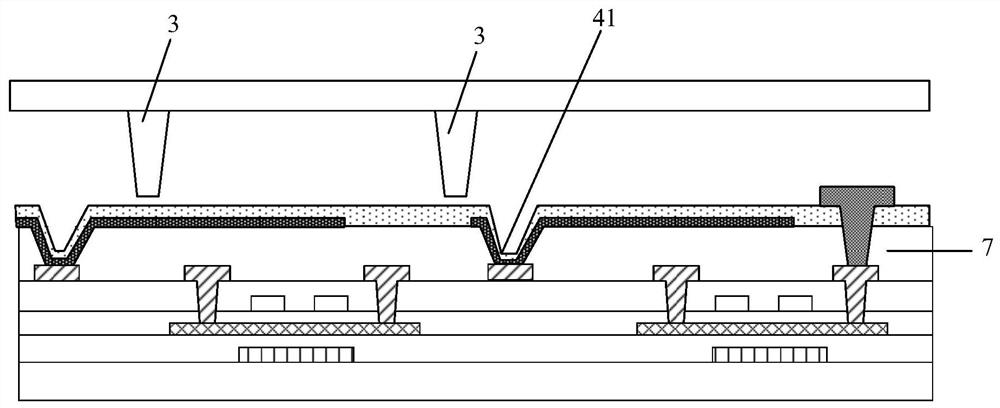
[0030] This embodiment provides a display panel, such as image 3 As shown, it includes an array substrate and a counter substrate, and a plurality of spacers 3 arranged between the array substrate and the counter substrate; A plurality of first via holes 41 are arranged on the planarization layer 7 , and the orthographic projections of the spacers 3 and the first via holes 41 on the substrate have no overlapping area.
[0031] In the display panel of this embodiment, it is defined that the relative position of the spacer 3 and the first via hole 41 on the array substrate to the base has no overlapping orthographic projection, so that the spacer 3 will not fall into the first via hole 41, so the support between the array substrate and the opposite substrate will not be lost, and the display panel can be avoided from collapsing.
Embodiment 2
[0033] This embodiment provides a display panel, such as Figure 4 , Figure 5 As shown, among them, Figure 4 for top view, Figure 5 along Figure 4 Cross-sectional view of B-B'. It includes an array substrate and an opposite substrate, and a plurality of spacers 3 arranged between the array substrate and the opposite substrate. The array substrate includes a base, and a planarization layer 7 disposed on the side of the base close to the opposite substrate, the planarization layer 7 is provided with a passivation layer 8 on the side close to the opposite substrate, and the first via hole 41 runs through the The passivation layer 8 and the planarization layer 7; the orthographic projection of the spacer 3 and the first via hole 41 on the substrate has no overlapping area.
[0034] The opposite substrate in this embodiment may also be a color filter substrate, see Figure 5 The color filter substrate includes a red, green and blue (RGB) pixel area and a black matrix area...
Embodiment 3
[0050] This embodiment provides a method for manufacturing a display panel, including the following steps:
[0051] S01. Provide a pair of opposite substrates; specifically, the opposite substrate may also be a color filter substrate, and the color filter substrate includes a red, green and blue (RGB) pixel area and a black matrix area.
[0052] S02, forming a planarization layer on the substrate, and forming a plurality of first via holes on the planarization layer to obtain an array substrate.
[0053] S03 , forming a plurality of spacers; wherein, the spacers can be disposed on the array substrate, or can be disposed on the opposite substrate, specifically, generally, the spacers are disposed in regions corresponding to the black matrix.
[0054] S04 , boxing the opposing substrate and the array substrate to obtain a display panel, wherein the spacer has no overlapping area with the orthographic projection of the first via hole to the substrate.
PUM
| Property | Measurement | Unit |
|---|---|---|
| size | aaaaa | aaaaa |
Abstract
Description
Claims
Application Information
 - R&D
- Intellectual Property
- Life Sciences
- Materials
- Tech Scout
- Unparalleled Data Quality
- Higher Quality Content
- 60% Fewer Hallucinations
Browse by: Latest US Patents, China's latest patents, Technical Efficacy Thesaurus, Application Domain, Technology Topic, Popular Technical Reports.
© 2025 PatSnap. All rights reserved.Legal|Privacy policy|Modern Slavery Act Transparency Statement|Sitemap|About US| Contact US: help@patsnap.com


