A thin keyboard switch

A keyboard switch, thin technology, applied in electrical switches, contact operating mechanisms, electrical components, etc., can solve problems such as unsmooth use, insufficient elasticity of metal sheets, affecting normal use, etc., to increase the pressing feel, improve user experience, The effect of enhancing balance

Inactive Publication Date: 2019-02-12
DONGGUAN CITY KAIHUA ELECTRONICS
View PDF7 Cites 0 Cited by
  • Summary
  • Abstract
  • Description
  • Claims
  • Application Information

AI Technical Summary

Problems solved by technology

Existing thin keyboard switches that use metal sheets as moving contacts are relatively insufficient in elasticity and lack of pressing feel due to the limitation of the internal space of the switch.
Manufacturers continue to make improvements in various aspects such as metal sheet materials and shapes to increase the pressing experience, but they have been limited to the improvement of pressing touch
At the same time, the keyboard switch has poor stability during use, resulting in unsmooth use and affecting normal use

Method used


Image

  • A thin keyboard switch
  • A thin keyboard switch
  • A thin keyboard switch

Examples


Embodiment 1

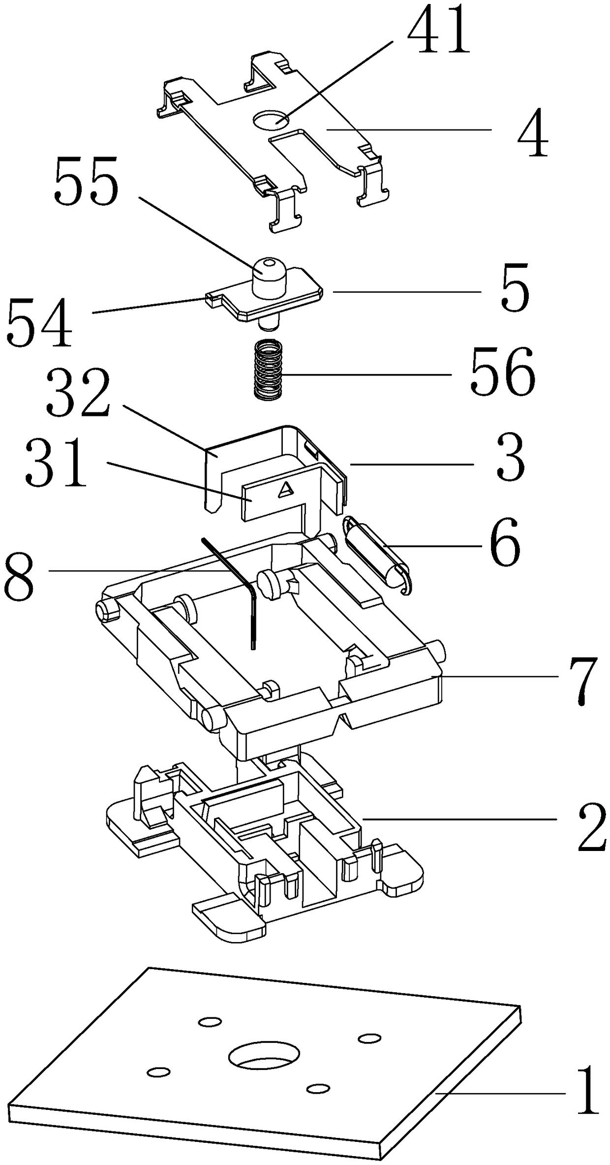
[0024] Please refer to Figure 1 to Figure 5 , the embodiment of the present invention provides a thin keyboard switch, including a PCB board 1, a base 2 arranged on the PCB board 1, and a conduction component 3 and an upper cover 4 respectively arranged on the base 2, and also includes respectively The guide core assembly 5, the extension spring 6 and the X-shaped bracket 7 arranged on the base 2, the base 2 is provided with a first accommodation groove 21 and a second accommodation groove 22, and the extension spring 6 is clamped on the In the first accommodating groove 21, the guide core assembly 5 and the conduction assembly 3 are clamped in the second accommodating groove 22, and the upper cover 4 is provided with an opening 41 for the upper end of the guide core assembly 5 to pass through; The upper edge of the base 2 is provided with a support plate seat 23, the X-shaped bracket 7 is arranged on the support plate seat 23, and is surrounded by the periphery of the base 2...

Embodiment 2

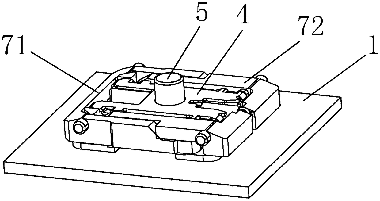
[0033] Please refer to Image 6 and Figure 7 The main difference between this embodiment and Embodiment 1 is that the guide core assembly 5' includes a guide core active part 51 and a guide core follower 52 inserted into the lower end of the guide core active part 51, and the conduction assembly 3 ' is a turtle carrier, which is located at the lower end of the guide core follower 52.

[0034] The working principle of this embodiment is: press the guide core active part 51, apply a downward force to the guide core follower 52, make the guide core follower 52 contact with the turtle carrier, and realize the conduction of the keyboard switch; Pressing the guide core active part 51, the guide core active part 51 drives the guide core follower 52 to return to the initial position upwards, so that the guide core follower 52 is separated from the tortoise carrier, and the keyboard switch is disconnected.

[0035] The key points of the present invention are mainly: by adding extens...


PUM


Abstract

A thin keyboard switch, comprising a PCB (1), a base (2) provided on the PCB, and a guiding component (3) and a cover (4), separately provided on the base, and further comprising a guide core component (5), a tension spring (6) and an X-shaped frame (7) all separately provided on the base, the base having provided therein a first accommodating groove (21) and a second accommodating groove (22), the tension spring being clamped in the first accommodating groove, the guide core component and the guiding component both being clamped in the second accommodating groove, and the cover having provided therein an opening (41) allowing a top end of the guide core component to penetrate; a support plate (23) is provided around a perimeter of a top end of the base, the X-shaped frame being provided on the support plate and surrounding an outer perimeter of the base, an end of the tension spring being hooked on the X-shaped frame; a bottom end of the cover is inserted into a gap formed by the X-shaped frame and the base. The thin keyboard switch of the present invention increases balance and stability while making the overall thickness thereof thinner, and also has a good feel when pressed, improving user experience.

Description

technical field [0001] The invention relates to a keyboard switch, in particular to a thin keyboard switch. Background technique [0002] Many operations of electronic devices require the use of keyboard switches as input means. The quality of the keyboard switch determines the experience of the input device, which requires the keyboard switch to have a good feel and sound. Existing thin keyboard switches that use metal sheets as movable contacts are relatively insufficient in elasticity and lack of pressing feel due to the limitation of the internal space of the switch. Manufacturers continue to make improvements in various aspects such as metal sheet materials and shapes to increase the pressing experience, but they have been limited to the improvement of pressing touch. At the same time, the keyboard switch has poor stability during use, resulting in unsmooth use and affecting normal use. Contents of the invention [0003] In view of the above deficiencies, the purpos...

Claims


Application Information

Patent Timeline
Patent Type & Authority Patents(China)
IPC IPC(8): H01H3/12H01H13/20H01H13/85
CPCH01H3/125H01H13/20H01H13/85H01H2215/054
Inventor 吴福喜
Owner DONGGUAN CITY KAIHUA ELECTRONICS
Why Eureka
Try Eureka