Distance-adjustable left aurcle plugging device

An occluder and distance adjustment technology, which is applied in medical science, surgery, ligation, etc., can solve the problems of plaque shedding, too short, and reducing the effectiveness and reliability of the device

Pending Publication Date: 2017-03-08
HANGZHOU NUOMAO MEDTECH CO LTD
View PDF15 Cites 7 Cited by
  • Summary
  • Abstract
  • Description
  • Claims
  • Application Information

AI Technical Summary

Problems solved by technology

The double-disk occluder of this technical solution is not significantly different from the conventional occluder, but the anchoring area of ​​the left atrial appendage is increased by implanting a metal stent to prevent the occluder from falling off, but the anchor cannot be adjusted according to the anatomical structure of the left atrial appendage. The distance between the fixed disk and the sealing disk, the double-disc occluder can move freely in the axial direction between the proximal end surface and the distal end surface of the metal stent, which will cause the waist of the double-disc occluder to be too long or too short , the occluder is deformed after deployment, resulting in poor sealing of the sealing disc
At the same time, the ideal implantation state of the sealing disc and the anchoring disc in this technical solution is when the two are parallel, but in the actual use process, the sealing disc or the anchoring disc will be deformed to a certain extent, or the sealing disc and the anchoring disc will be deformed to a certain extent. There will be a torque at the connection position, once this happens, it will reduce the effectiveness and reliability of the device
[0007] In the above technology, the distance between the anchoring disk and the sealing disk is fixed and not adjustable. At the same time, the sealing disk and the anchoring disk are rigidly connected. However, due to individual differences, each patient’s tissue defect or need to be blocked The position and shape are different, and the fixed distance and rigid connection are often not well adapted to complex and changeable clinical needs. For example, taking the left atrial appendage occluder as an example, the implantation position of the anchoring disc has an If the anchoring disc is implanted too deeply, the sealing disc will be squeezed and deformed, and the edge will be lifted, resulting in residual shunt. If the entry is too shallow, the sealing disc cannot adhere to the atrial wall, and it will also cause residual shunt
[0008] If you encounter the above-mentioned situation where the release position of the anchor plate is improper, you need to take out the anchor plate and select the release position again, but the anchor plate generally has barbs to prevent it from falling off. Repeated removal and release of the anchor plate will make the anchor The barbs on the plate cause damage to the inner wall of the left atrial appendage or the plaque falls off, forming a thrombus, which not only prolongs the operation time, increases the pain of the patient, but also increases other iatrogenic risks

Method used


Image

  • Distance-adjustable left aurcle plugging device
  • Distance-adjustable left aurcle plugging device
  • Distance-adjustable left aurcle plugging device

Examples


Embodiment 1

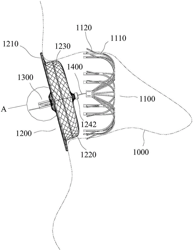
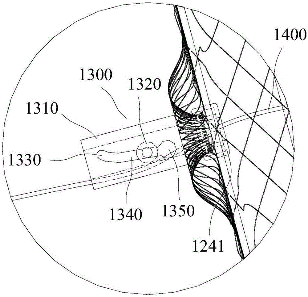
[0084] Such as figure 1 , Figure 4 As shown, the adjustable left atrial appendage occluder includes an anchoring device 1100 and a sealing disc 1200 arranged separately. The anchoring device 1100 is connected with a traction cable 1400 that runs through the sealing disc 1200. The traction cord 1400 is provided with an anti-loosening device. 1300, and the anti-loosening part 1300 abuts against the side of the sealing disc 1200 facing away from the anchoring device 1100. The anchoring device 1100 is at the distal end (the end away from the operator), and the sealing disc 1200 is at the proximal end (the end closer to the operator).

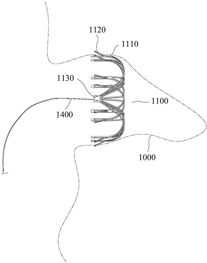
[0085] Anchoring device 1100 adopts prior art, such as figure 1 , image 3 , Figure 4 As shown, the anchoring part 1110 includes a plurality of support rods, one end of each support rod is converged and fixed to form a central end 1130, and the other end radially spreads outwards, then bends and extends toward the convergent end to form a fit ...

Embodiment 2

[0107] The difference between this embodiment and embodiment 1 is that, as Figure 5 As shown, the anti-loosening member 2300 is engaged with the pulling rope 2400 in a buckle manner.

[0108] Such as Figure 5 As shown, anti-off nodes 2411 are arranged on the traction cable 2400, and the anti-off nodes 2411 can be formed by knotting the traction cable 2400, or can be formed by thermal melting, injection molding, crimping or welding. In this embodiment, the traction cable 2400 is made of 2-0 polyester multi-strand wires, and is knotted to form a detachment prevention node 2411 .

[0109] The spacing of the anti-separation nodes 2411 can be selected according to needs, and they can be arranged at the far end of the pulling rope 2400 at equal or uneven intervals. When the anti-detachment nodes 2411 are arranged at unequal intervals, the distance near the far end of the traction cable 2400 is smaller.

[0110] To a large extent, the distance between the anti-off nodes 2411 det...

Embodiment 3

[0120] The difference with embodiment 2 is that, as Figure 7 As shown, there are two traction cables 3400, and each traction cable 3400 is provided with an anti-separation node 3410. The anti-separation node 3410 is spherical, and other forms can also be adopted.

[0121] The smallest hole diameter of the tapered through hole 3310 of the anti-off part 3300 only allows one pull rope 3400 and one anti-off node 3410 to pass through at the same time, and does not allow two anti-off nodes 3410 to pass through at the same time. The arrangement of two traction cables 3400 can ensure the reliability of backstopping, that is, prevent the traction cables 3400 from passing through the anti-escape member 3300 in reverse.

[0122] The release process of this embodiment is the same as that of Embodiment 2, and the state after release is as follows Figure 8 , Figure 9 As shown, two traction cables 3400 are fixedly connected between the sealing disc 3200 and the anchoring device 3100, an...


PUM


Abstract

The invention discloses an distance-adjustable left aurcle plugging device. The distance-adjustable left aurcle plugging device includes an anchoring device and a sealing disc which are separately arranged. The anchoring device is connected with a pulling cable penetrating through the sealing disc, and the sealing disc is provided with an anti-disengaging member acting on the sealing disc. The anti-disengaging member is fixedly connected with the sealing disc or is integrally formed with the sealing disc or is connected with the sealing disc in an abutted mode. The pulling cable is connected with the axle center position of the anchoring device, and the sealing disc is provided with a through hole used for allowing the pulling cable to penetrate through. The through hole is located at the axis position of the sealing disc, the pulling cable is of a flexible structure, and one pulling cable is arranged or a plurality of pulling cables are arranged side by side. The provided distance-adjustable left aurcle plugging device can adjust the distance between the anchoring device and the sealing disc based on the shape of the left aurcle, so that the sealing disc can completely block the left atrium and the left auricle.

Description

technical field [0001] The invention relates to the field of interventional medical devices, in particular to an adjustable distance left atrial appendage occluder. Background technique [0002] The occluder is used as an implant in interventional therapy for the treatment of congenital heart diseases such as atrial septal defect, ventricular septal defect and patent ductus arteriosus, as well as for the treatment of patients with atrial fibrillation. Currently clinical occluders include atrial / ventricular septal defect occluders, left atrial appendage occluders, etc. [0003] Existing occluders all adopt an integrated design, and when in use, each disc body cannot be selected according to the difference in the position and size of the patient's focus, and the distance between each disc body of the occluder cannot be adjusted. [0004] Studies have confirmed that more than 90% of thrombi in patients with non-valvular atrial fibrillation form in the left atrial appendage, an...

Claims


Application Information

Patent Timeline
Patent Type & Authority Applications(China)
IPC IPC(8): A61B17/12
CPCA61B17/12122A61B17/12172A61B2017/00526A61B2017/12054
Inventor 张庭超李阳王永胜
Owner HANGZHOU NUOMAO MEDTECH CO LTD
Why Eureka
Try Eureka