A microstructure cemented carbide turning insert for cutting superalloy gh4169

A GH4169, cemented carbide technology, used in cutting inserts, tools for lathes, turning equipment, etc., can solve problems such as reducing cutting temperature, and achieve the effect of increasing contact area, improving durability, and obvious cooling effect.

Active Publication Date: 2018-10-09
GUIZHOU UNIV
View PDF9 Cites 0 Cited by
  • Summary
  • Abstract
  • Description
  • Claims
  • Application Information

AI Technical Summary

Problems solved by technology

From the above, it can be seen that there is no structural design on how to reduce the cutting temperature on the near-field of the cutting edge in the industry.

Method used


Image

  • A microstructure cemented carbide turning insert for cutting superalloy gh4169
  • A microstructure cemented carbide turning insert for cutting superalloy gh4169
  • A microstructure cemented carbide turning insert for cutting superalloy gh4169

Examples


Embodiment 1

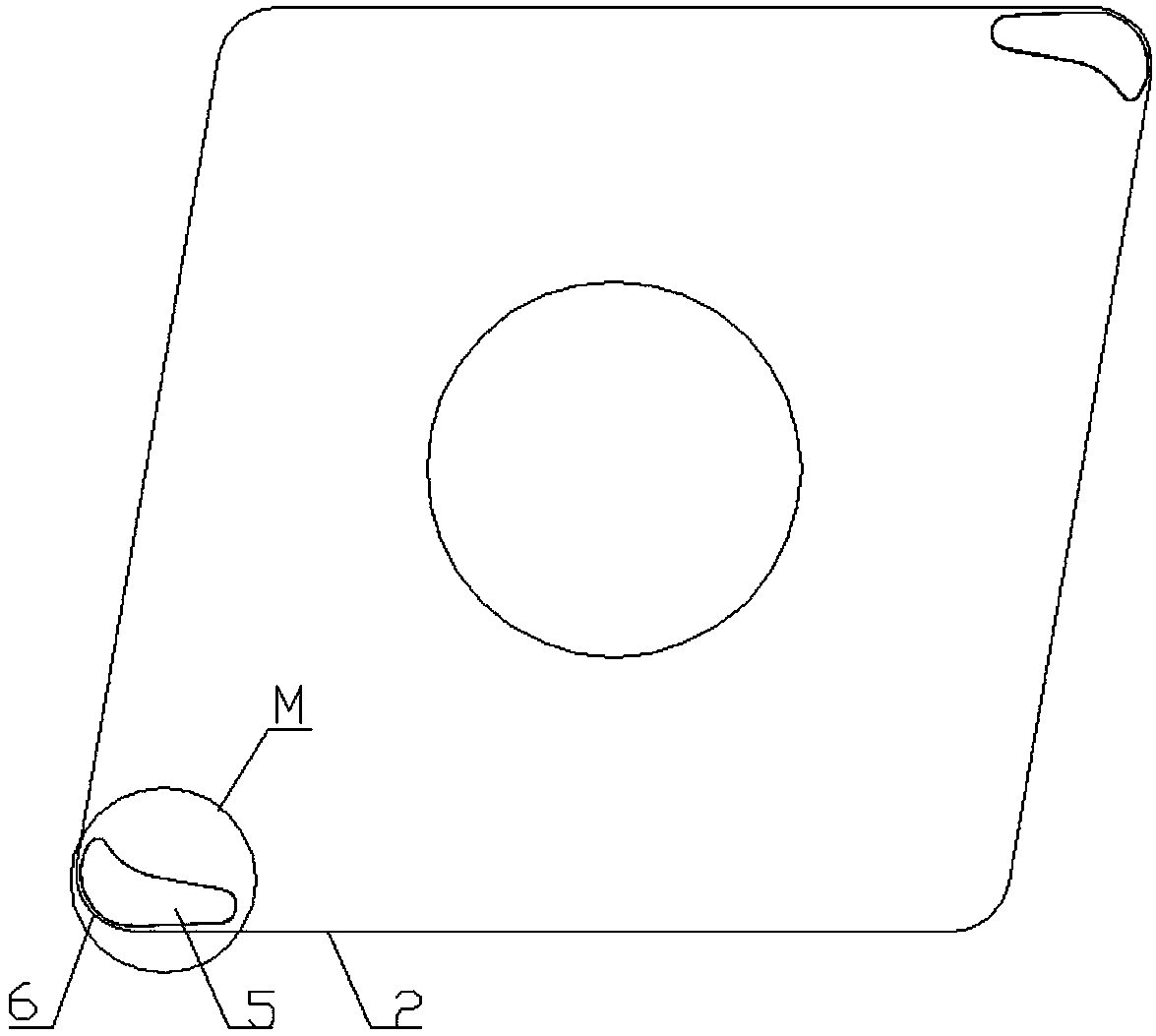
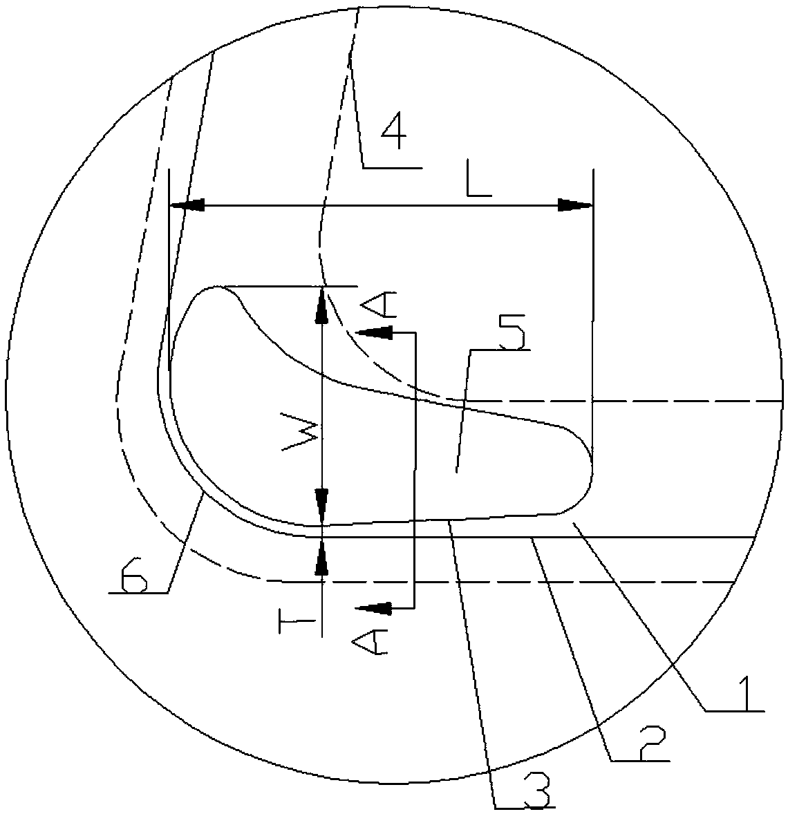
[0031] Example 1. A kind of microstructure cemented carbide turning blade for cutting superalloy GH4169, its composition is as follows figure 1 As shown, including the rake face 1, the edge of the rake face 1 is provided with a main cutting edge 2, and the cutting edge of the rake face 1 is provided with a microgroove 5 near the region 4; the microgroove 5 is asymmetrical and integral J-shaped microstructures with unequal widths and unequal depths (such as figure 2 shown).

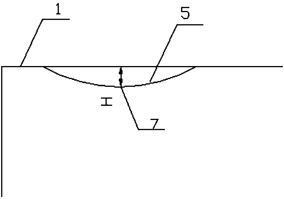
[0032] Aforesaid microgroove 5 (as Figure 3-5 As shown), the section on the rake face 1 is asymmetrical curve, the bottom surface 7 of the microgroove 5 is flat, and the maximum depth H of the microgroove 5 is 0.27-0.34mm.

[0033] The length L of aforementioned microgroove 5 is 2.15~2.66mm; The maximum width W of microgroove 5 (as figure 2 Shown) is 0.89 ~ 1.21mm.

[0034] The minimum distance T (such as figure 2 shown) is 0.06~0.09mm.

[0035] The connection form between the outer edge 3 of the ...


PUM

PropertyMeasurementUnit
lengthaaaaaaaaaa
widthaaaaaaaaaa

Abstract

The invention discloses a microstructure hard alloy turning blade cutting high temperature alloy GH4169. The microstructure hard alloy turning blade cutting the high temperature alloy GH4169 comprises a front blade face (1). The edge of the front blade face (1) is provided with a main cutting edge (2). A microgroove (5) is formed at the position of a cutting edge near area (4) of the front blade face (1). The microgroove (5) is of a dissymmetrical J-shaped microstructure which is equal in width and different in depth on the whole. The microstructure hard alloy turning blade cutting the high temperature alloy GH4169 has the advantages of lowering the cutting temperature and improving the durability of a tool.

Description

technical field [0001] The invention relates to a cutting tool used in the field of cutting processing, in particular to a microstructure hard alloy turning blade for cutting superalloy GH4169. Background technique [0002] Cutting is the main means of material removal in the machinery manufacturing industry, and the quality of cutting tools directly affects the efficiency and quality of cutting. In the cutting process, the cutting edge is the main part of removing material, the cutting edge and the rake face area near the cutting edge (the near area of ​​the cutting edge refers to the small area on the rake face of the tool close to the cutting edge, such as figure 2 The area surrounded by the middle dotted line) has the worst working environment, and its structure is directly related to the durability of the tool, the efficiency of machining and the quality of machining, so the reasonable design of the cutting edge and the near-field structure of the cutting edge is partic...

Claims


Application Information

Patent Timeline
Patent Type & Authority Patents(China)
IPC IPC(8): B23B27/14
CPCB23B27/14B23B2200/0447B23B2200/086B23B2222/28
Inventor 刘勇何林邹中妃蒋宏婉占刚吴锦行杨薪玉
Owner GUIZHOU UNIV
Why Eureka
Try Eureka