passenger conveyor

A technology for passenger conveyors and frames, used in transportation and packaging, escalators, etc., and can solve problems such as damage

Active Publication Date: 2019-08-23
HITACHI BUILDING SYST CO LTD
View PDF7 Cites 0 Cited by
  • Summary
  • Abstract
  • Description
  • Claims
  • Application Information

AI Technical Summary

Problems solved by technology

[0003] At these triangular intersections, if an object protrudes from the passenger conveyor moving from the lower floor to the upper floor over the railing to the outside of the passenger conveyor, the object will be clamped into the triangular intersection, so that either the object or the passenger conveyor both parties may be damaged

Method used


Image

  • passenger conveyor
  • passenger conveyor
  • passenger conveyor

Examples


Embodiment 1

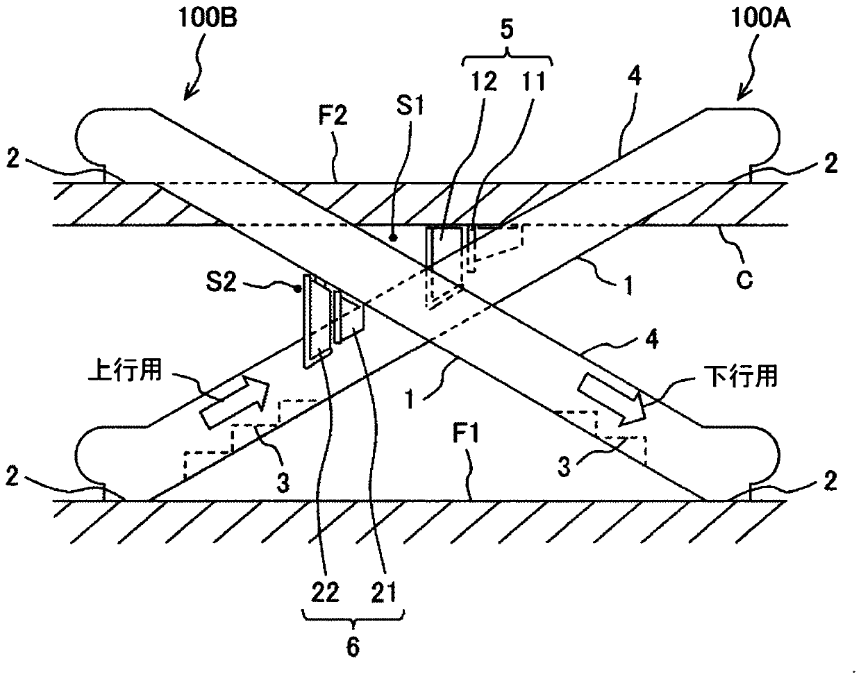
[0027] figure 1 It is a schematic structural diagram related to one embodiment of the passenger conveyor to which the present invention is applied.

[0028] In this embodiment, two passenger conveyors 100A and 100B are arranged in parallel between the floor surface F1 of the lower floor and the floor surface F2 of the upper floor of the building. The passenger conveyor 100A is for upward travel, and the passenger conveyor 100B is for downward travel. Each conveyor 100A, 100B comprises: a frame body 1 erected between the lower floor surface F1 and the upper floor surface F2; passenger upper and lower floors 2 respectively arranged on the lower floor surface F1 and the upper floor surface F2; Steps 3 that are endlessly connected in the frame body 1 and circulate between the upper and lower floors 2 of each passenger; a driving device (not shown) that drives the steps 3; installed in the frame body 1 and arranged along the forward direction of the steps 3 The railings 4 on both...

Embodiment 2

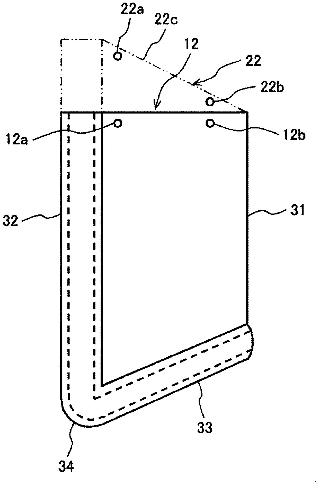
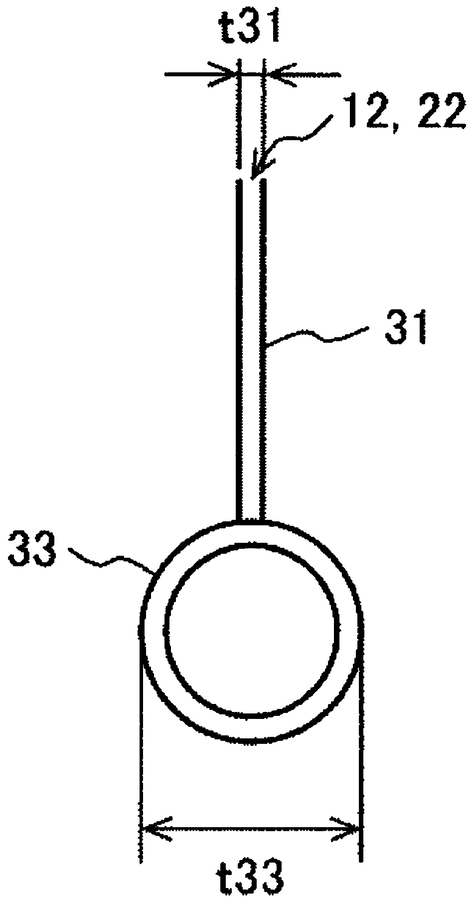
[0042] Figure 5 It is a figure which shows the triangle plate of the passenger conveyor concerning Example 2 of this invention. Image 6 It is a longitudinal cross-sectional view showing an example of the shape of the gusset according to the second embodiment. Figure 7 It is a longitudinal cross-sectional view showing an example of the shape of the gusset according to the second embodiment. Figure 8 It is a longitudinal cross-sectional view showing an example of the shape of the gusset according to the second embodiment. exist Figure 5 in, with figure 2 Similarly, the parts of the movable warning panel 22 that are different from the movable warning panel 12 are indicated by dotted lines.

[0043] The movable warning panels 12 and 22 of the second embodiment are composed of a plate-shaped member 41 and a cylindrical member 42 attached to the front edge of the plate-shaped member 41 . The lower edge portion of the plate member 41 is bent in a curved manner to form a se...


PUM


Abstract

It is an object of the present invention to provide a passenger conveyor which can more easily pull back an object sandwiched below a triangular guard. A curved member such as a cylindrical member (33) is provided at a lower edge of the triangular guard (12, 22) on a passenger conveyor having a triangular guard (12, 22) arranged at a triangular cross section, Is formed between the lower ceiling and the railing, or two passenger conveyors arranged side by side, which is formed between the frame of the passenger conveyor of the side and the railing of the other passenger conveyor.

Description

technical field [0001] The present invention relates to a passenger conveyor installed so as to connect a lower floor surface and an upper floor surface. Background technique [0002] Since the passenger conveyor is installed in such a way that the opening opened in the lower ceiling (upper floor) is connected to connect the lower floor and the upper floor, the moving A triangular crossing portion is formed between railings of the passenger conveyor of the handrail (hereinafter, the crossing portion of the above-mentioned shape is referred to as a “triangular crossing portion”). Moreover, when two passenger conveyors are installed side by side, a triangular intersection is formed between the handrail of one passenger conveyor and the frame of the other passenger conveyor. [0003] At these triangular intersections, if an object protrudes from the passenger conveyor moving from the lower floor to the upper floor over the railing to the outside of the passenger conveyor, the ...

Claims


Application Information

Patent Timeline
Patent Type & Authority Patents(China)
IPC IPC(8): B66B23/00B66B29/00
CPCB66B23/00B66B29/00
Inventor 铃木健永
Owner HITACHI BUILDING SYST CO LTD
Why Eureka
Try Eureka