
Waste incineration device with smoke pipe cooling structure and implementation method of waste incineration device

A technology of waste incineration and cooling structure, which is applied in the direction of combustion methods, separation methods, chemical instruments and methods, etc., which can solve the problems of easy blockage of the filter screen, poor circulation, etc., and achieve the effect of reducing resistance and facilitating pull back

Active Publication Date: 2021-10-01
HAIAN TIANPENG MACHINERY MFG
View PDF8 Cites 0 Cited by
  • Summary
  • Abstract
  • Description
  • Claims
  • Application Information

AI Technical Summary

Problems solved by technology

[0003] However, when the current garbage incinerator is incinerated, a water circulation cooling device will be installed at the bottom of the smoke pipe to prolong the service life of the smoke pipe. However, after the water circulation cooling device absorbs heat, some impurities will be generated inside, which will easily block the filter. When the circulation is not smooth and the water circulation cannot be realized, the waves of the water flow hit the filter screen to dredge it to a certain extent.

Method used


Image

  • Waste incineration device with smoke pipe cooling structure and implementation method of waste incineration device
  • Waste incineration device with smoke pipe cooling structure and implementation method of waste incineration device
  • Waste incineration device with smoke pipe cooling structure and implementation method of waste incineration device

Examples


Embodiment approach

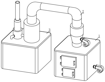
[0036] The present invention provides another technical solution: a method for implementing a waste incineration device with a flue pipe cooling structure, comprising the following steps:

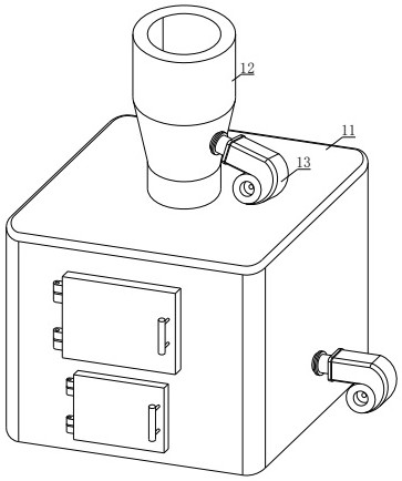
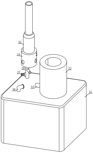
[0037] S01: The incinerator 11 starts to incinerate, the heat of the flue gas heats the aqueous solution in the inner cavity of the steam chamber 346, and the generated steam enters the push chamber 347 through the steam pipe 345, and at the same time, the steam pushes the first rotating wheel 3481, and the rotation of the first rotating wheel 3481 drives the second rotating wheel. One tooth 3483, the first tooth 3483 makes the third gear 3484 rotate, the third gear 3484 pushes the connecting rod 3486 through the crankshaft 3485, and the connecting rod 3486 pushes the water wave assembly 3472;

[0038] S02: The first push plate 34721 installed at the lower end of the water wave component 3472 pushes the water solution in the water solution cooling chamber 349 to generate waves, and the waves...


PUM


Abstract

The invention discloses a waste incineration device with a smoke pipe cooling structure and an implementation method of the waste incineration device. The waste incineration device comprises an incineration device body, a first connecting pipe and a smoke exhaust device, a second sliding groove is formed in the bottom face of an inner cavity of a pushing chamber, a water wave assembly is installed in an inner cavity of the second sliding groove, a water solution of a water solution cooling chamber continuously forwards slaps a filter screen in a wavy shape, and therefore the situation that impurities generated after the water solution in an inner cavity of the water solution cooling chamber absorbs heat block the filter screen to affect filtration can be avoided. The implementation method of the waste incineration device with the smoke pipe cooling structure is further disclosed. Waves move forwards to push a second push plate, the second push plate enables a spiral shaft to move forwards through a telescopic pipe, a cleaning brush rotates to brush the filter screen, the effect that the cleaning brush conducts brushing together under wave slapping is achieved, and therefore the water solution circulates.

Description

technical field [0001] The invention relates to the technical field of a smoke pipe cooling device, in particular to a garbage incineration device with a smoke pipe cooling structure and an implementation method thereof. Background technique [0002] The garbage incinerator is a device for incinerating garbage. The garbage burns in the furnace and becomes waste gas, which enters the secondary combustion chamber, burns completely under the forced combustion of the burner, and then enters the spray dust collector. After dust removal, it is discharged into the atmosphere through the chimney . When the waste incinerator is incinerated, the flue gas will contain a large amount of heat energy. After the heat passes through the exhaust pipe at the bottom, it will heat the exhaust pipe for a long time, thereby reducing the service life of the smoke pipe. [0003] However, when the current garbage incinerator is incinerated, a water circulation cooling device will be installed at th...

Claims


Application Information

Patent Timeline
Patent Type & Authority Applications(China)
IPC IPC(8): F23G5/00F23G5/44F23J15/06F23J15/02B01D46/10B01D46/00
CPCF23G5/00F23G5/44F23J15/06F23J15/025B01D46/10
Inventor 朱纯陈家来孟祥勇
Owner HAIAN TIANPENG MACHINERY MFG
Learn More