Direct push plate flow regulating damping cylinder for intelligent knee joint

A flow regulation and knee joint technology, applied in the field of hydraulic damping cylinder, can solve the problems of difficult processing, increased power consumption, large volume and weight, etc., to avoid failure to work, reduce complexity, and achieve continuous damping adjustment.

Active Publication Date: 2018-06-26
上海理工资产经营有限公司
View PDF13 Cites 0 Cited by
  • Summary
  • Abstract
  • Description
  • Claims
  • Application Information

AI Technical Summary

Problems solved by technology

[0004] Patent No. 201370655 discloses an electronically controlled hydraulic damping cylinder for prosthetic limbs. Although this patent realizes the separate adjustment of flexion and extension, it requires two motors to control the corresponding valves, resulting in larger volume and weight and increased power consumption.
[0005] Patent application number 2016102229387 discloses a single-motor controlled prosthetic knee joint electronically controlled hydraulic damping cylinder structure, which is exquisite in structure but difficult to process
[0006] Patent Publication No. CN102065799A discloses a semi-driven prosthetic knee joint device, which realizes driving and non-driving modes through hydraulic pumps and motors, but the hydraulic valve circuit is particularly complicated, and the hydraulic pumps and motors make the structure complex and heavy
[0007] The above-mentioned inventions all use a rotary motor to control the rotation of the valve stem to achieve flow adjustment, and there is no structure that uses a linear motor to translate the valve stem for flow adjustment.

Method used


Image

  • Direct push plate flow regulating damping cylinder for intelligent knee joint
  • Direct push plate flow regulating damping cylinder for intelligent knee joint
  • Direct push plate flow regulating damping cylinder for intelligent knee joint

Examples


Embodiment Construction

[0020] The present invention will be described in detail below in conjunction with the accompanying drawings.

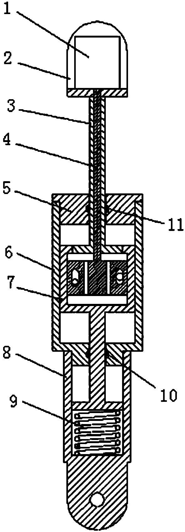
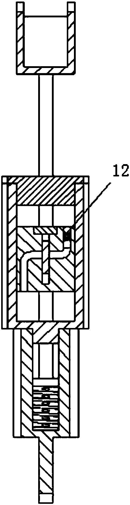
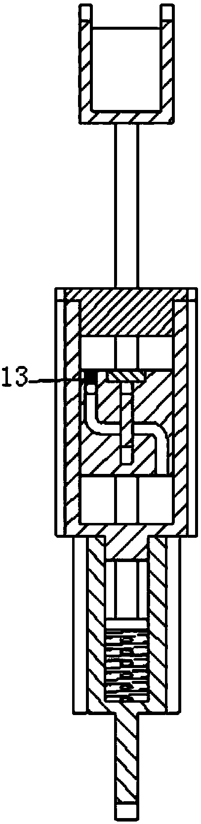
[0021] Such as Figure 1 to Figure 3 As shown, a direct-push plate type flow regulating damping cylinder for intelligent knee joints provided by the present invention includes a linear motor 1, a motor bracket 2, a hollow piston rod 3, a plate valve body 4, a hydraulic cylinder upper cover 5, and a hydraulic cylinder Cylinder body 6, hollow piston block 7, spring case 8, extension spring 9, seal ring A10, seal ring B11, check valve A12, check valve B13.

[0022] One end of the hydraulic cylinder block 6 is fixedly connected to the upper cover 5 by threads, and the other end is fixedly connected to the spring shell 8 by threads. The spring shell 8 is placed with a stretching spring 9, and the hydraulic cylinder block 6 is equipped with a hollow piston block 7 and a hollow piston block 7. One end is connected to the extension spring 9 through the piston rod, and the o...


PUM


Abstract

The invention relates to a direct-push plate-type flow-regulating damping cylinder for intelligent knee joints, which includes a motor bracket, a hollow piston rod, a plate-type valve body, a hydraulic cylinder upper cover, a hydraulic cylinder body, a hollow piston block, a spring shell, and an extension aid. Spring, one end of the hydraulic cylinder body is fixedly connected to the upper cover through threads, and the other end is fixedly connected to the spring shell through threads, and an extension spring is placed in the spring shell, and a hollow piston block is installed in the hydraulic cylinder body, and one end of the hollow piston block passes through the piston rod Connect the extension spring, and the other end is connected to the motor bracket through the hollow piston rod. The plate valve body is installed in the hollow piston block. The plate valve body is provided with two parallel flat key-shaped holes and circular holes parallel up and down. There are hydraulic oil flow passages parallel to each other which are respectively bent and stretched, and the two hydraulic oil flow passages are arranged at staggered heights along the axial direction, and the two hydraulic oil flow passages are respectively provided with check valves. The invention can realize two-way independent control of the bending and extension damping of the prosthetic knee joint through a linear motor.

Description

technical field [0001] The invention relates to a hydraulic damping cylinder for a prosthetic knee joint, in particular to a direct-push plate-type flow regulating damping cylinder structure for an intelligent knee joint. Background technique [0002] Smart knee joints refer to knee joint prostheses that use microprocessors to control damping, and the adjustment of knee joint damping mainly includes hydraulic pressure, air pressure, and magnetorheology. Both hydraulic and pneumatic intelligent knee joints use microprocessors to drive motors to adjust the opening of the valve inside the damping cylinder to adjust the damping; magnetorheological intelligent knee joints change the strength of the magnetic field by changing the magnitude of the current to make the magnetic current The viscosity of the variable fluid changes, thereby adjusting the damping. The hydraulic knee joint can provide a large torque in the support phase, but the flexibility is not very high in the swing ...

Claims


Application Information

Patent Timeline
Patent Type & Authority Patents(China)
IPC IPC(8): A61F2/60A61F2/64A61F2/68
CPCA61F2/60A61F2/64A61F2/68A61F2002/5003A61F2002/5033A61F2002/5072A61F2/74A61F2/741A61F2/748
Inventor 曹武警魏小东李文秀邵海存黄小海王峰王孟喻洪流孟青云孟巧玲
Owner 上海理工资产经营有限公司
Why Eureka
Try Eureka