A fan blade type flow regulating damping cylinder for intelligent knee joint

A technology of flow regulation and knee joint, applied in the direction of spring/shock absorber, medical science, shock absorber, etc., can solve problems such as failure to reach the designated position, unsmooth, large axial load of the motor, etc., to avoid failure of damping adjustment , to avoid motor out of step, the effect of continuous damping adjustment

Active Publication Date: 2022-01-25
UNIV OF SHANGHAI FOR SCI & TECH
View PDF7 Cites 0 Cited by
  • Summary
  • Abstract
  • Description
  • Claims
  • Application Information

AI Technical Summary

Problems solved by technology

The magnetorheological smart knee joint adjusts the damping effect by changing the current to change the magnetic field strength, but the viscosity change of the magnetorheological fluid is closely related to the magnetic field, and it has high requirements on the material of the magnetorheological fluid, which is not easy to control and is not easy Increase production capacity
Both hydraulic pressure and air pressure use a microprocessor to drive the motor to adjust the valve opening of the damping cylinder, so as to achieve the purpose of adjusting the damping, but the stability of the pneumatic knee joint support performance is not reliable, which is likely to cause safety accidents
[0003] At present, there are few structural designs for intelligent knee joint hydraulic damping cylinders in China. Related technical documents include: Patent No. 105769395A and Patent No. 106726028B both propose electronically controlled hydraulic damping cylinder structures for intelligent knee joint prostheses, but there are The shafts of the motor, the regulating valve body and the piston are in a straight line and are connected or in contact with each other, so that the motor receives a large axial load during the operation of the knee joint. During the adjustment process, it is easy to lose step and fail to reach the specified position, which seriously affects the knee joint. Performance issues with joint damping adjustments
Although the electronically controlled hydraulic damping cylinder structure proposed by Patent No. 106539633A avoids the problem of excessive axial load on the motor, the hydraulic flow path in the piston block is complicated and difficult to process
Patent No. 102065799A discloses a semi-driven prosthetic knee joint device, which realizes driving and non-driving modes through hydraulic pumps and damping adjustment valves, but the hydraulic valve circuit is very complicated, and the hydraulic pump and electric motor make the structure complex and heavy
Patent No. 201370655 and Patent No. 107035808A, although these two patents realize the separate adjustment of flexion and extension, but need two motors to control the corresponding valves, which makes the volume and weight larger and power consumption increased
Patent No. 109806036A realizes a motor to realize the two-way control of hydraulic damping, but the clearance fit between the designed valve body and the adjusting seat will lead to the formation of oil film in the gap for a long time, and the tension generated by the oil film will make the damping of the valve body too large when it rotates and the rotation will not rotate. Smooth, damping adjustment is not accurate.

Method used


Image

  • A fan blade type flow regulating damping cylinder for intelligent knee joint
  • A fan blade type flow regulating damping cylinder for intelligent knee joint
  • A fan blade type flow regulating damping cylinder for intelligent knee joint

Examples


Embodiment Construction

[0017] In order to make the technical means, creative features, goals and effects achieved by the present invention easy to understand, the present invention will be described in detail below in conjunction with the embodiments and accompanying drawings.

[0018]

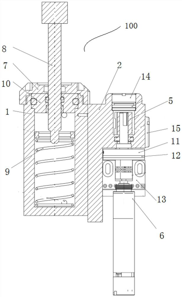
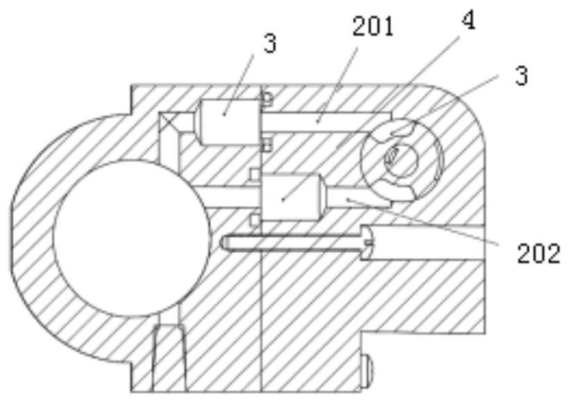
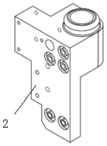
[0019] figure 1 It is an overall schematic diagram of a fan-type flow regulating damping cylinder for smart knee joints in an embodiment of the present invention. figure 2 It is a cross-sectional view of a fan-type flow-regulating damping cylinder for a smart knee joint in an embodiment of the present invention. image 3 It is a schematic diagram of the damping adjustment seat in the embodiment of the present invention. as well as Figure 4 It is a sectional view of the damping adjustment seat in the embodiment of the present invention.

[0020] like Figure 1 to Figure 4 As shown, a fan-type flow regulating damping cylinder for intelligent knee joint provided in this embodiment includes: a cylinder body 1, a...


PUM


Abstract

The invention relates to the field of wheelchairs, and discloses a fan-type flow regulating damping cylinder for intelligent knee joints, which is used to control the flow of hydraulic oil to adjust the damping degree of the knee joints. It is characterized in that it includes: a cylinder body with The first chamber and the second chamber are isolated from each other by the push rod; the damping adjustment seat, installed on the cylinder body, has an expansion hydraulic passage and a buckling hydraulic passage respectively communicated with the first chamber and the second chamber; the first The one-way valve is used to prevent the hydraulic oil in the second chamber from flowing backward; the second check valve is used to prevent the hydraulic oil in the first chamber from flowing backward; Between the channels, the DC servo motor is installed on the damping adjustment seat to drive the reversing valve to rotate; among them, the DC servo motor drives the reversing valve to rotate to control the flow cross section of the stretching hydraulic channel and the buckling hydraulic channel, thereby adjusting the damping cylinder degree of damping.

Description

technical field [0001] Embodiments of the present invention relate to the field of wheelchairs, in particular to a fan-type flow regulating damping cylinder for a smart knee joint. Background technique [0002] The smart knee joint refers to controlling the damper of the knee joint through a microcomputer to control the speed of the swing phase and the stability of the support phase at the same time, so that the gait of a lower limb patient is closer to that of a healthy person when wearing a prosthesis, with higher following and symmetry . At present, there are mainly three ways to adjust damping in smart knee joints: magneto-rheological, pneumatic and hydraulic. The magnetorheological smart knee joint adjusts the damping effect by changing the current to change the magnetic field strength, but the viscosity change of the magnetorheological fluid is closely related to the magnetic field, and it has high requirements on the material of the magnetorheological fluid, which is...

Claims


Application Information

Patent Timeline
Patent Type & Authority Patents(China)
IPC IPC(8): A61F2/64A61F2/74F16F9/19F16F9/32F16F9/34
CPCA61F2/64A61F2/68F16F9/19F16F9/34F16F9/3242F16F9/3207A61F2002/5004A61F2002/5033A61F2/74
Inventor 张哲文汪晓铭喻洪流孟巧玲徐晓英肖艺璇孙金悦蓝贺
Owner UNIV OF SHANGHAI FOR SCI & TECH
Why Eureka
Try Eureka