Device and method for testing unscrewing of self-locking nuts of grouped movable supporting plates

A technology of self-locking nuts and floating pallets, which is applied in the direction of measuring devices, testing of mechanical components, testing of machine/structural components, etc., and can solve the problem that self-locking nuts of floating pallets in groups cannot be applied, etc.

Inactive Publication Date: 2020-05-08
河南航天精工制造有限公司
View PDF5 Cites 0 Cited by
  • Summary
  • Abstract
  • Description
  • Claims
  • Application Information

AI Technical Summary

Problems solved by technology

[0004] The purpose of the present invention is to provide a test device for unscrewing self-locking nuts of grouped floating pallets to solve the problem that the test device in the prior art cannot be applied to the structure without rivet holes on the bracket and a plurality of self-locking nuts are arranged side by side on the bracket For the technical problem that the self-locking nuts of the groups of traveling pallets cannot be applied, the present invention also provides a test method for unscrewing the self-locking nuts of the group of traveling pallets

Method used


Image

  • Device and method for testing unscrewing of self-locking nuts of grouped movable supporting plates
  • Device and method for testing unscrewing of self-locking nuts of grouped movable supporting plates
  • Device and method for testing unscrewing of self-locking nuts of grouped movable supporting plates

Examples


Embodiment Construction

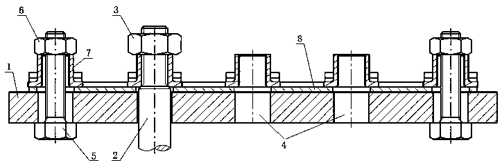
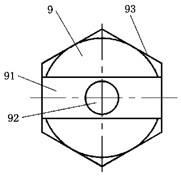
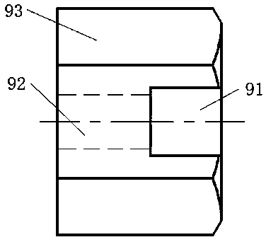
[0033] In order to make the object, technical solution and advantages of the present invention clearer, the present invention will be further described in detail below in conjunction with the accompanying drawings and embodiments. It should be understood that the specific embodiments described here are only used to explain the present invention, and are not intended to limit the present invention, that is, the described embodiments are only some of the embodiments of the present invention, but not all of the embodiments. The components of the embodiments of the invention generally described and illustrated in the figures herein may be arranged and designed in a variety of different configurations.

[0034] Accordingly, the following detailed description of the embodiments of the invention provided in the accompanying drawings is not intended to limit the scope of the claimed invention, but merely represents selected embodiments of the invention. Based on the embodiments of the...


PUM


Abstract

The invention relates to a device and a method for testing unscrewing of self-locking nuts of grouped movable supporting plates. The device comprises a rigid fixing plate, a convex shoulder loading bolt and a loading nut, wherein more than three through holes are formed in the rigid fixing plate, and each through hole is used for corresponding to a respective self-locking nut mounting position ona self-locking nut bracket. The device further comprises at least two groups of bolt assemblies or at least two fastening bolts. The bolt assemblies are used for penetrating through the correspondingthrough holes in the rigid fixing plate and the corresponding self-locking nuts so as to fix the self-locking nut supports to the rigid fixing plate; and the fastening bolts are used for penetrating through the corresponding through holes in the rigid fixing plate and screwed into the corresponding self-locking nuts. According to the device and the method, the self-locking nut bracket is fixed onthe rigid fixing plate, so that the integral fixation of the self-locking nuts of the grouped movable supporting plates without rivet hole structures is realized, and the unscrewing test of the grouped movable supporting plate self-locking nuts without rivet hole structures and with a plurality of self-locking nuts arranged on the bracket is realized.

Description

technical field [0001] The invention belongs to the technical field of fasteners, and in particular relates to a test device for unscrewing self-locking nuts of grouped floating pallets. Background technique [0002] In the connecting structure of aerospace vehicles, due to the small opening spacing of the connecting structure of the substrate and the limitation of the space position, ordinary self-locking nuts and self-locking nuts such as single-ear, double-ear, and angle-shaped pallets cannot be installed. In order to meet the structural connection requirements, a group of floating pallet self-locking nuts is designed, that is, multiple pallet self-locking nuts are arranged side by side on a bracket. [0003] In the prior art, such as the loading bolt disclosed by the Chinese utility model patent whose authorized announcement number is CN202748185U and the pallet self-locking nut using the loading bolt, when the test device is in use, the bracket of the pallet self-lockin...

Claims


Application Information

Patent Timeline
IPC IPC(8): G01M13/00G01N3/22G01N3/02
CPCG01M13/00G01N3/02G01N3/22G01N2203/0021G01N2203/027
Inventor 王立俊马建华李旭健柯书忠朱婉婉胡庆宽黄帅孙晓军
Owner 河南航天精工制造有限公司
Why Eureka
Try Eureka