
A reduction shaft transmission device

A transmission device and reduction shaft technology, applied in the field of transmission shafts, can solve the problems of affecting the life of needle roller bearings, unreliable positioning, easy movement of the inner ring, etc., achieve simplified structure and assembly process, simple structure, improved reliability and The effect of running stability

Active Publication Date: 2017-06-09
HUNAN NANFANG AVIATION HIGH ACCURATE DRIVE
View PDF5 Cites 0 Cited by
  • Summary
  • Abstract
  • Description
  • Claims
  • Application Information

AI Technical Summary

Problems solved by technology

First of all, the transmission mechanism of this structure needs to be installed with a retaining ring for the hole, and two needle roller bearings with inner and outer rings are installed in series, which is difficult to assemble; secondly, the left gear uses the needle roller bearing for axial positioning through the retaining ring for the hole, because Needle roller bearings have inner and outer rings, while the retaining ring for the hole only positions the outer ring of the bearing, and the inner ring is easy to move
Positioning is unreliable and affects needle roller bearing life

Method used


Image

  • A reduction shaft transmission device
  • A reduction shaft transmission device

Examples


Embodiment Construction

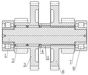
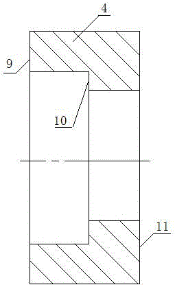
[0012] The reduction shaft transmission device of the present invention includes a transmission shaft 1 , a needle bearing 2 , a left gear 3 , a right gear 6 , and a cylindrical roller bearing 8 . A needle roller bearing spacer 4 and a drive shaft middle spacer 5 are arranged between the left gear 3 and the right gear 6 to axially locate the left gear 3 . The needle roller bearing spacer 4 is a cylindrical inner stepped spacer composed of the first end face 9, the second end face 10 and the third end face 11. The first end face 9, the second end face 10 and the third end face 11 are respectively connected with the left gear 3 , The needle roller bearing 2 is in contact with the spacer sleeve 5 in the transmission shaft. A cylindrical roller bearing spacer 7 is arranged between the right gear 6 and the cylindrical roller bearing 8 to axially locate the right gear 6 .

[0013] In order to simplify the structure and assembly process of the needle roller bearing 2, the needle rol...


PUM


Abstract

The invention relates to a transmission device of a speed-reducing shaft. The transmission device of the speed-reducing shaft comprises a transmission shaft, a needle bearing, a left gear, a right gear and a cylindrical roller bearing, and is characterized in that a needle bearing spacer and a transmission shaft middle spacer are arranged between the left gear and the right gear so as to axially position the left gear; a cylindrical roller bearing spacer is arranged between the right gear and the cylindrical roller bearing so as to axially position the right gear. The transmission device of the speed-reducing shaft is simple in structure and easy to manufacture; the outer circumferential surface of the transmission shaft and the inner circumferential surface of the left gear are taken as an inner runway and an outer runway, which are provided with retainers, of the needle bearing; the needle bearing spacer adopts an internal step-type structure and plays the dual role of a needle spacer and an axial spacer, so that the structure and the assembling process are simplified, and the assembling difficulty and the manufacturing cost are reduced; through spacer positioning, the axial load of the needle bearing is avoided, so that the reliability and the running stability of the transmission device are improved, and the service life of the transmission device of the speed-reducing shaft is effectively prolonged; therefore, the transmission device of the speed-reducing shaft is highly economical.

Description

technical field [0001] The invention relates to a transmission shaft, in particular to a reduction shaft transmission device in a harvester gearbox. Background technique [0002] The reduction shaft in the harvester gearbox is used as an idler shaft to drive the left and right drive wheels at the same time, which is a more important reduction transmission mechanism in the harvester gearbox. The reduction shaft transmission mechanism of the existing harvester is made up of transmission shaft, cylindrical roller bearing, washer, combined needle roller bearing, left gear, hole retaining ring, right gear. First of all, the transmission mechanism of this structure needs to be installed with a retaining ring for the hole, and two needle roller bearings with inner and outer rings are installed in series, which is difficult to assemble; secondly, the left gear uses the needle roller bearing for axial positioning through the retaining ring for the hole, because Needle roller bearing...

Claims


Application Information

Patent Timeline
Patent Type & Authority Patents(China)
IPC IPC(8): F16H57/023
CPCF16H57/023
Inventor 卢璋李荣满胡云波何奇刘芳
Owner HUNAN NANFANG AVIATION HIGH ACCURATE DRIVE
Learn More