Orthogonal Flow Adjustment Damping Cylinder for Smart Knee

A flow adjustment and damping cylinder technology, applied in medical science, prosthesis, etc., can solve the problems of large volume and weight, increased power consumption, etc., and achieve the effects of continuous damping adjustment, reduced power consumption, and reduced structural weight.

Active Publication Date: 2018-06-26
UNIV OF SHANGHAI FOR SCI & TECH
View PDF13 Cites 1 Cited by
  • Summary
  • Abstract
  • Description
  • Claims
  • Application Information

AI Technical Summary

Problems solved by technology

[0006] Patent No. 201370655 discloses an electronically controlled hydraulic damping cylinder for prosthetics. Although this patent realizes the separate adjustment of flexion and extension, it requires two motors to control the corresponding valves, resulting in larger volume and weight and increased power consumption.

Method used


Image

  • Orthogonal Flow Adjustment Damping Cylinder for Smart Knee
  • Orthogonal Flow Adjustment Damping Cylinder for Smart Knee
  • Orthogonal Flow Adjustment Damping Cylinder for Smart Knee

Examples


Embodiment Construction

[0020] The present invention will be described in detail below in conjunction with the drawings.

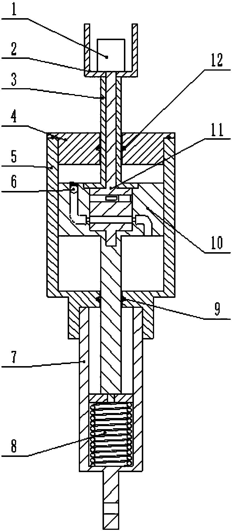
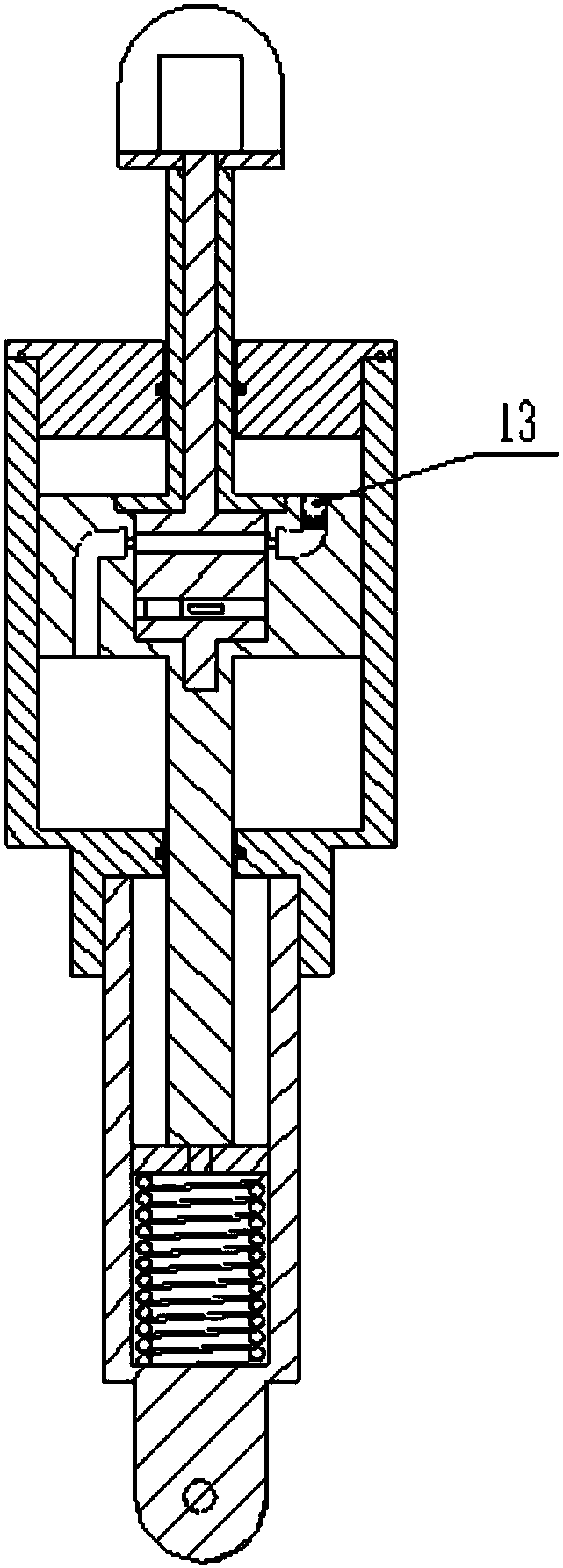
[0021] Such as Figure 1 to Figure 5 As shown, the present invention provides an orthogonal flow adjustment damping cylinder for smart knee joints, including stepping motor 1, motor bracket 2, piston rod body 3, upper cover 4, cylinder body 5, check valve A6, The spring housing 7, the extension spring 8, the sealing ring 9, the hollow piston 10, the spiral valve body 11, the sealing ring 12, and the one-way valve 13.

[0022] One end of the cylinder body 5 is screwed to the upper cover 4, and the other end is connected to the spring shell 7. The cylinder body 5 is equipped with a hollow piston 10, which has an orthogonal flow regulating oil passage, and a check valve 6 is arranged in the orthogonal flow passage. For the check valve 13, the front end of the piston rod of the hollow piston 10 is in contact with the extension spring 8 placed in the spring housing 7. The hollow piston 10...


PUM


Abstract

The invention relates to an orthogonal flow regulating damping cylinder for intelligent knee joints, comprising a cylinder body and a hollow piston, one end of the cylinder body is threadedly connected to an upper cover, and the other end is connected to a spring shell, and a hollow piston is installed in the cylinder body. The front end of the piston rod of the hollow piston is in contact with the stretching spring placed in the spring shell. The hollow piston is equipped with a spiral valve body. The side wall of the hollow piston is provided with an orthogonal flow channel, and a check valve is arranged in the orthogonal flow channel. By rotating the spiral valve body, the flow areas of the hydraulic oil passages in the left and right chambers of the damping cylinder are successively changed, thereby changing the flow rate of the left and right chambers of the damping cylinder. The invention can realize two-way independent control of the bending and extension damping of the prosthetic knee joint through a motor.

Description

Technical field [0001] The invention relates to a hydraulic damping cylinder structure for a prosthetic knee joint, in particular to an orthogonal flow adjustment damping cylinder structure for an intelligent knee joint. Background technique [0002] Smart knee joint refers to a knee joint prosthesis that uses microprocessor control damping, and the adjustment of knee joint damping mainly includes hydraulic pressure, air pressure, and magnetorheological changes. The hydraulic and pneumatic smart knee joints use a microprocessor-driven motor to adjust the valve opening of the damping cylinder to achieve damping adjustment; the magnetorheological smart knee joint changes the strength of the magnetic field by changing the current to make the magnetic current The viscosity of the fluid changes to adjust the damping. The hydraulic knee joint can provide a larger torque during the support period, but the flexibility during the swing period is not very high; the pneumatic knee joint ha...

Claims


Application Information

Patent Timeline
Patent Type & Authority Patents(China)
IPC IPC(8): A61F2/70A61F2/74
CPCA61F2/68A61F2002/701A61F2/74A61F2/741A61F2/748
Inventor 魏小东曹武警赵伟亮李文秀霍金月李新伟喻洪流孟青云孟巧玲
Owner UNIV OF SHANGHAI FOR SCI & TECH
Why Eureka
Try Eureka