Electro-hydraulic damping cylinder structure for intelligent knee joint

An electronically controlled hydraulic, knee joint technology, applied in medical science, prosthesis, etc., can solve the problems of difficult manufacturing, many connecting rods, complex holes, etc. Effect

Active Publication Date: 2017-07-18
上海理工资产经营有限公司
View PDF1 Cites 0 Cited by
  • Summary
  • Abstract
  • Description
  • Claims
  • Application Information

AI Technical Summary

Problems solved by technology

However, this structure uses a middle fixed block, and the pistons on both sides move, making the volume larger
Moreover, there are many connecting rods, the channels are complicated, and it is difficult to process and manufacture

Method used


Image

  • Electro-hydraulic damping cylinder structure for intelligent knee joint
  • Electro-hydraulic damping cylinder structure for intelligent knee joint

Examples


Embodiment Construction

[0019] The present invention will be described in detail below in conjunction with the accompanying drawings.

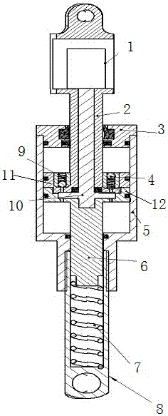
[0020] Such as figure 1 As shown, the present invention provides an electronically controlled hydraulic damping cylinder structure for intelligent knee joints, which includes an upper piston part 2 with a hollow piston rod and an upper piston block 11 with a hole, placed on the upper piston part 2 The upward-opening check valve 9 and the downward-opening check valve 4 in the hole of the upper piston block 11 are placed in the hollow piston rod of the piston part 2 and are directly connected to the upper stepping motor 1 through the valve core rod. shaped valve plate 10, the lower piston part 6 with the lower piston rod and the lower piston block 12 with holes, the cylinder body 5 of the opening, the cylinder cover 3 connected to the opening of the cylinder body, the spring case connected with the lower end of the cylinder body 5 8, the spring 7 placed in the spring ...


PUM


Abstract

The invention relates to an electronically controlled hydraulic damping cylinder structure for intelligent knee joints. The upper piston part has a hollow piston rod and an upper piston block located at the lower end of the hollow piston rod. The upper piston block is provided with hydraulic oil in two upper and lower chambers. channels, the hydraulic oil channels of the two upper and lower chambers are respectively equipped with one-way valves with opposite blocking directions; the lower piston part has a lower piston rod and a lower piston block located at the upper end of the lower piston rod, and the lower piston block is provided with two A fan-shaped hole is used as the hydraulic oil channel of the upper and lower chambers. The upper piston block and the lower piston block are connected in the cylinder body. A butterfly valve plate is installed between the upper piston block and the lower piston block. The butterfly valve plate is placed through the hollow piston rod. The inner spool rod is connected to the stepper motor, and the stepper motor controls the rotation of the butterfly valve plate to change the flow area of ​​the hydraulic oil channel in the upper and lower chambers of the lower piston block, thereby changing the flow rate of the upper and lower chambers of the hydraulic cylinder. The structure enables bidirectional independent control of the prosthetic knee joint flexion and extension damping through a single motor.

Description

technical field [0001] The invention relates to a hydraulic damping cylinder structure for a prosthetic knee joint, in particular to an electronically controlled hydraulic damping cylinder structure for an intelligent knee joint. Background technique [0002] Smart knee joints refer to knee joint prostheses that use microprocessors to control damping, and the adjustment of knee joint damping mainly includes hydraulic pressure, air pressure, and magnetorheology. Both hydraulic and pneumatic intelligent knee joints use microprocessors to drive motors to adjust the opening of the valve inside the damping cylinder to adjust the damping; magnetorheological intelligent knee joints change the strength of the magnetic field by changing the magnitude of the current to make the magnetic current The viscosity of the variable fluid changes, thereby adjusting the damping. The hydraulic knee joint can provide a large torque in the support phase, but the flexibility is not very high in th...

Claims


Application Information

Patent Timeline
Patent Type & Authority Patents(China)
IPC IPC(8): A61F2/70A61F2/74
CPCA61F2/68A61F2002/701A61F2/74A61F2/741A61F2/748
Inventor 曹武警赵伟亮李瑨王振平喻洪流孟巧玲
Owner 上海理工资产经营有限公司
Why Eureka
Try Eureka