
Power supply plugging system

A technology for power supply plugging and electrical connection, applied in the field of electric power, can solve the problems of endangering the personal safety of equipment, failing to work normally, and accidentally kicking and bumping the plug, and achieves the effect of convenient locking and unlocking, preventing electrical disconnection, and preventing accidents.

Active Publication Date: 2017-04-26
陕西康斯特唯电气工程有限公司
View PDF5 Cites 40 Cited by
  • Summary
  • Abstract
  • Description
  • Claims
  • Application Information

AI Technical Summary

Problems solved by technology

[0002] Due to the importance of electrical equipment, a reliable and stable electrical connection is often required between some electrical equipment and power supply equipment. However, in existing work and life, the plug of electrical equipment is only inserted into the socket of the power supply socket. The insertion force between the plug and the jack is used to realize the electrical connection. There are no other locking parts on the plug or in the jack. Due to the walking of the workers, the plug will usually be accidentally kicked and bumped, and the plug will be separated from the jack. The power is cut off after plugging in, which leads to the power failure of the electrical equipment and cannot work normally. In serious cases, it will endanger the equipment and personal safety.

Method used


Image

  • Power supply plugging system
  • Power supply plugging system
  • Power supply plugging system

Examples


Embodiment Construction

[0017] The preferred embodiments of the present invention will be described in detail below in conjunction with the accompanying drawings, so that the advantages and features of the present invention can be more easily understood by those skilled in the art, so as to define the protection scope of the present invention more clearly.

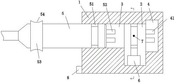
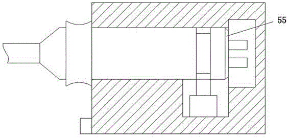
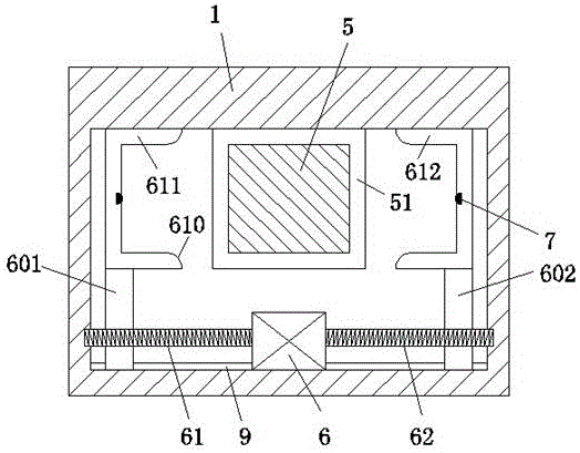
[0018] refer to Figure 1-5 As shown, a power supply plug-in system of the present invention includes a housing 1 and a travel cavity 2 arranged in the housing 1, the left side of the travel cavity 2 communicates with a plug sliding cavity 3, the The right side of the walking cavity 2 is provided with a power supply socket 4, the power supply socket 4 is provided with a power supply jack 41, and the plug device of the electric equipment is slidably arranged in the plug sliding chamber 3, and the plug device includes a plug body 5, and the holding block 53 arranged on the plug body 5, and the square lock groove 51 arranged on the plug body 5, and ...


PUM


Abstract

The invention discloses a power supply plugging system. The system comprises a shell (1) and a walking cavity (2) arranged inside the shell (1). The left side of the walking cavity (2) is communicated with a plug sliding cavity (3). A power supply base (4) is arranged on the right side of the walking cavity (2). A power supply socket (41) is arranged in the power supply base (4). A plug device of electrical equipment is arranged in a sliding manner in the plug sliding cavity (3). The plug device includes a plug body (5), a holding block (53) arranged on the plug body (5), a square lock slot (51) arranged on the plug body (5), and an electrical connector (52) arranged on the right side face of the plug body (5). The electrical connector (52) is used for being connected with the power supply socket (41) to supply power. The edge of the right side face of the plug body (5) is provided with a guide slope (55).

Description

technical field [0001] The invention relates to the field of electric power, in particular to a power supply plug-in system. Background technique [0002] Due to the importance of electrical equipment, a reliable and stable electrical connection is often required between some electrical equipment and power supply equipment. However, in existing work and life, the plug of electrical equipment is only inserted into the socket of the power supply socket. The insertion force between the plug and the jack is used to realize the electrical connection. There are no other locking parts on the plug or in the jack. Due to the walking of the workers, the plug will usually be accidentally kicked and bumped, and the plug will be separated from the jack. Power outage due to plugging, which leads to power outage of electrical equipment and cannot work normally. In serious cases, it will endanger equipment and personal safety. Contents of the invention [0003] The technical problem to b...

Claims


Application Information

Patent Timeline
Patent Type & Authority Applications(China)
IPC IPC(8): H01R13/629H01R13/639H01R24/00
CPCH01R13/629H01R13/639H01R24/00
Inventor 朱亚伟
Owner 陕西康斯特唯电气工程有限公司
Learn More