
Control method and device for automatic emergency braking of vehicle, and vehicle

An automatic emergency braking and vehicle technology, which is applied in the field of control devices for vehicles and automatic emergency braking control devices for vehicles, can solve problems such as the speed of obstacles in front of them, the discomfort of people in the vehicle, and the lack of vehicle braking force. , to avoid the accidental start of emergency braking, improve the driving experience, and optimize the realization method.

Active Publication Date: 2017-05-10
ZHICHEAUTO TECH BEIJING
View PDF5 Cites 28 Cited by
  • Summary
  • Abstract
  • Description
  • Claims
  • Application Information

AI Technical Summary

Problems solved by technology

[0004] In the process of realizing the present invention, the inventor found that: for the implementation of the above-mentioned AEBS whose deceleration varies from small to large, the probability of collision with the obstacle in front is relatively high, such as the situation where an obstacle suddenly inserts into the front of the vehicle in front of the side of the vehicle In this situation, the vehicle has a higher chance of colliding due to insufficient braking force; for the above-mentioned AEBS implementation scheme in which the braking force gradually decreases from a larger value, since this implementation scheme does not take into account the obstacles ahead when calculating the braking distance Therefore, there may be a phenomenon that the braking operation is performed when there is no need for braking. In addition, the gradual reduction of the braking force from a large value will easily make the occupants feel uncomfortable.

Method used


Image

  • Control method and device for automatic emergency braking of vehicle, and vehicle
  • Control method and device for automatic emergency braking of vehicle, and vehicle
  • Control method and device for automatic emergency braking of vehicle, and vehicle

Examples


Embodiment Construction

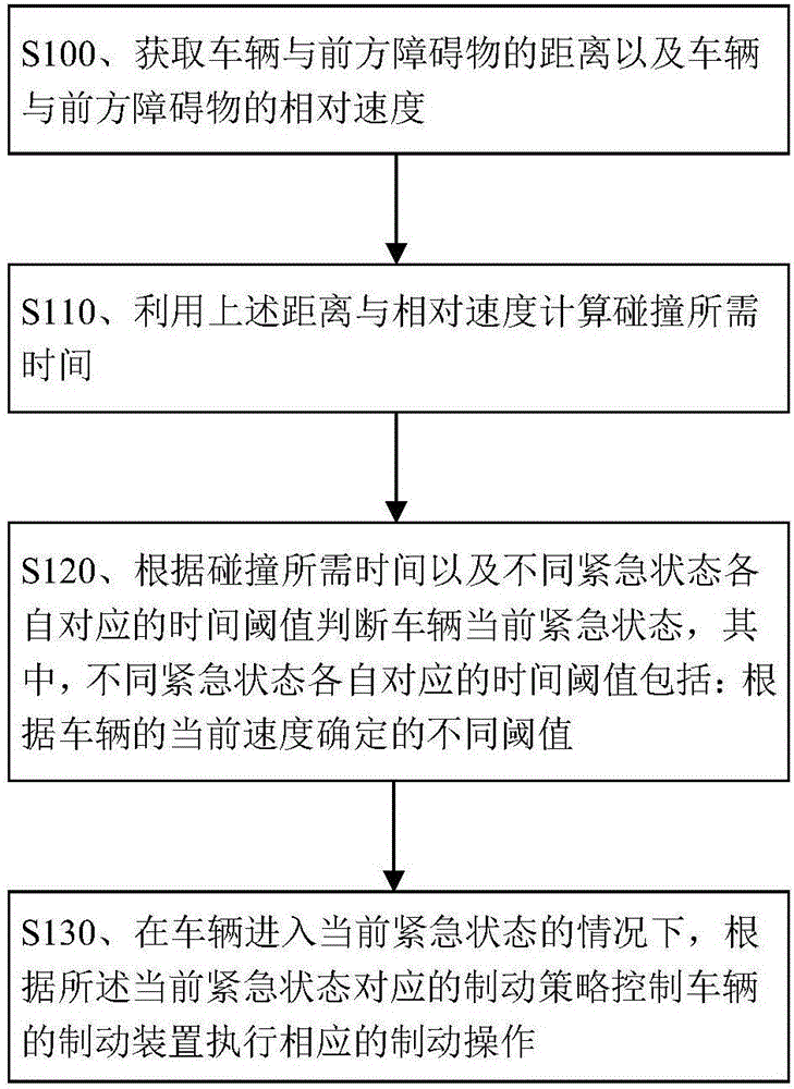
[0057] Exemplary embodiments of the present disclosure will be described in more detail below with reference to the accompanying drawings. Although exemplary embodiments of the present disclosure are shown in the drawings, it should be understood that the present disclosure may be embodied in various forms and should not be limited to the embodiments set forth herein. On the contrary, these embodiments are provided to enable a more thorough understanding of the technical solution of the present invention, and to fully convey the scope of the disclosure of the present invention to those skilled in the art.

[0058] The following is a specific embodiment of the control method for automatic emergency braking of a vehicle according to the present invention.

[0059] The control method for automatic emergency braking of a vehicle in this embodiment is applicable to a motor vehicle supporting the AEBS function, and the method is executed while the vehicle is running. The flow proce...


PUM


Abstract

The invention discloses a control method and device for automatic emergency braking of a vehicle, and the vehicle. The method comprises the steps of obtaining the distance between the vehicle and a barrier in front of the vehicle as well as the relative speed of the vehicle and the barrier in front of the vehicle, working out the time before a collision occurs according to the distance and the relative speed, judging the current emergency state of the vehicle according to the time before the collision occurs and time threshold values corresponding to different emergency states, and before the vehicle enters the current emergency state, controlling a braking device of the vehicle to carry out corresponding braking operation according to the braking strategy corresponding to the current emergency state, specifically, the time threshold values corresponding to the different emergency states include the different time threshold values determined according to the current speed of the vehicle. By means of the technical scheme, the implementation method of an advanced emergency braking system (AEBS) is optimized, and the driving and taking experience of the vehicle is improved while vehicle safety is fully guaranteed.

Description

technical field [0001] The invention relates to vehicle braking technology, in particular to a control method for automatic emergency braking of vehicles, a control device for automatic emergency braking of vehicles and a vehicle provided with the control device for automatic emergency braking of vehicles. Background technique [0002] AEBS (Advanced Emergency Braking System, Advanced Emergency Braking System) has been recognized in automobiles because it can automatically perform emergency braking operations in emergency situations (such as when there is a risk of collision) to avoid collisions or reduce the damage caused by collisions. more widely used. [0003] In practical applications, the AEBS implementation solutions provided by different AEBS suppliers are not exactly the same; Damage, when some AEBS is triggered, it will control its deceleration to gradually increase until the vehicle stops; for another example, some AEBS will determine the current speed based on t...

Claims


Application Information

Patent Timeline
Patent Type & Authority Applications(China)
IPC IPC(8): B60T7/22B60T8/1755
CPCB60T7/22B60T8/17558
Inventor 张鹏李机智刘瑞祥刘海明沈海寅
Owner ZHICHEAUTO TECH BEIJING
Learn More