Method for designing MIMO (Multiple-input multiple-output) radar transmitting direction diagram based on LFM (Linear Frequency Modulation) signals

A technology of emission pattern and design method, applied in the field of MIMO radar, can solve the problems of Doppler frequency sensitivity, affecting target detection, target gain decline of polycode signal, etc., and achieves Doppler sensitivity and Doppler tolerance. Effects of Features

Active Publication Date: 2017-05-10
XIDIAN UNIV
View PDF5 Cites 6 Cited by
  • Summary
  • Abstract
  • Description
  • Claims
  • Application Information

AI Technical Summary

Problems solved by technology

In the literature "Waveform synthesis for diversity-based transmitbeampattern design, IEEE Transactions on Signal Processing, 2008, 56, (6), pp.2593-2598," Peter Stoica and Li Jian et al. gave a polyphase code-based The MIMO radar transmit pattern design method, the method adjusts the phase of the transmit signal of each transmit array el

Method used


Image

  • Method for designing MIMO (Multiple-input multiple-output) radar transmitting direction diagram based on LFM (Linear Frequency Modulation) signals
  • Method for designing MIMO (Multiple-input multiple-output) radar transmitting direction diagram based on LFM (Linear Frequency Modulation) signals
  • Method for designing MIMO (Multiple-input multiple-output) radar transmitting direction diagram based on LFM (Linear Frequency Modulation) signals

Examples


Embodiment Construction

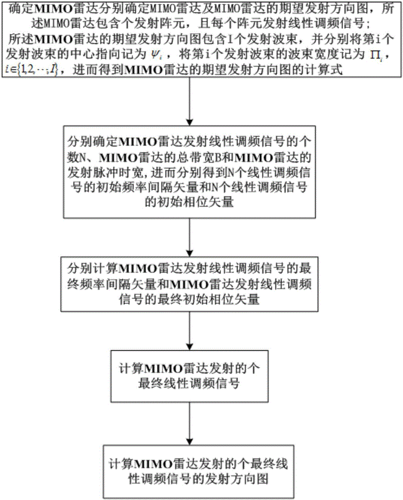
[0021] refer to figure 1 , is a flow chart of a method for designing a MIMO radar transmission pattern based on an LFM signal of the present invention; the method for designing a transmission pattern for a MIMO radar based on an LFM signal comprises the following steps:

[0022] Step 1, respectively determine the MIMO radar and the expected emission pattern of the MIMO radar, the MIMO radar includes N' transmitting array elements, and each array element transmits a chirp signal; the expected emission pattern of the MIMO radar includes I transmit beams, and denote the center point of the i-th transmit beam as ψ i , denote the beamwidth of the i-th transmit beam as Π i , i∈{1,2,…,I}, and then get the calculation formula P of the expected transmission pattern of MIMO radar d (θ); where θ represents the airspace angle of the MIMO radar, and N' and I are natural numbers respectively.

[0023] Specifically, determine the MIMO radar and the expected transmission pattern of the MIM...


PUM


Abstract

The invention discloses a method for designing an MIMO (Multiple-input multiple-output) radar transmitting direction diagram based on LFM (Linear Frequency Modulation) signals. The main idea comprises the steps of determining an MIMO radar and an expected transmitting direction diagram of the MIMO radar, wherein the MIMO radar comprises N' transmitting array elements, each array element transmits linear frequency modulation signals, the expected transmitting direction diagram of the MIMO radar comprises I transmitting wave beams; calculating a calculation formula of the expected transmitting direction diagram of the MIMO radar; respectively determining the number N of linear frequency modulation LFM signals transmitted by the MIMO radar, the total bandwidth B of the MIMO radar and the transmitting pulse time-width T' of the MIMO radar, respectively calculating an initial frequency interval vector delta(f0) of the N linear frequency modulation LFM signals and an initial phase vector delta(phi0) of the N linear frequency modulation LFM signals, and thus calculating N final linear frequency modulation LFM signals S transmitted by the MIMO radar; and sequentially calculating a covariance correlation matrix of the N final linear frequency modulation LFM signals transmitted by the MIMO radar and a transmitting direction diagram of the N final linear frequency modulation LFM signals transmitted by the MIMO radar according to the final linear frequency modulation LFM signals S.

Description

technical field [0001] The invention belongs to the technical field of MIMO radar, in particular to a method for designing a transmission pattern of a MIMO radar based on an LFM signal, that is, a multiple-input multiple-output (MIMO) signal based on a linear frequency modulation (Linear Frequency Modulation, LFM) signal. ) The design method of radar transmission pattern is suitable for the design of MIMO radar transmission energy diagram and the reasonable distribution of MIMO radar transmission energy. Background technique [0002] The concept of MIMO radar is a new radar system proposed in recent years, and it has become a research hotspot in the radar field at home and abroad. In the definition of MIMO radar, multi-input refers to transmitting multiple radar signal waveforms at the same time, and multi-output refers to receiving multiple antennas at the same time to obtain multi-channel spatial sampling signals. In MIMO radar, the transmit signal of each transmit array ...

Claims


Application Information

Patent Timeline
IPC IPC(8): G01S7/42
CPCG01S7/42
Inventor 赵永波李慧程增飞刘宏伟水鹏朗苏洪涛
Owner XIDIAN UNIV
Why Eureka
Try Eureka