Method for designing zero-setting waveform of LFM signal of MIMO radar

A waveform design and signal waveform technology, applied in the field of radar, can solve the problems of poor Doppler tolerance, loss, and susceptibility to interference of phase-encoded signals, achieve good Doppler tolerance, reduce the degree of mismatch, and improve the anti-interference ability. disturbing effects

Active Publication Date: 2019-06-28
XIDIAN UNIV
View PDF3 Cites 4 Cited by
  • Summary
  • Abstract
  • Description
  • Claims
  • Application Information

AI Technical Summary

Problems solved by technology

However, the disadvantage of this method is that although the transmitted energy of the designed LFM partial correlation waveform can cover the specified area, it still has enough power in the interference direction and still transmits energy in the interference direction, so it is easily affected by interference.
The energy of the waveform designed by this method is concentrated in the specified range and produces nulls in the interference direction. However, this method still has the disadvantage that the phase-encoded signal has the inherent defect of poor Doppler tolerance.
When the radar system transmits this type of waveform, if the detection target is a moving target, there will be a certain loss when pulse compression is performed at the receiving end, and the target cannot even be detected, which will seriously affect the target detection performance of the radar system

Method used


Image

  • Method for designing zero-setting waveform of LFM signal of MIMO radar
  • Method for designing zero-setting waveform of LFM signal of MIMO radar
  • Method for designing zero-setting waveform of LFM signal of MIMO radar

Examples


Embodiment Construction

[0035] The present invention will be further described below in conjunction with the drawings.

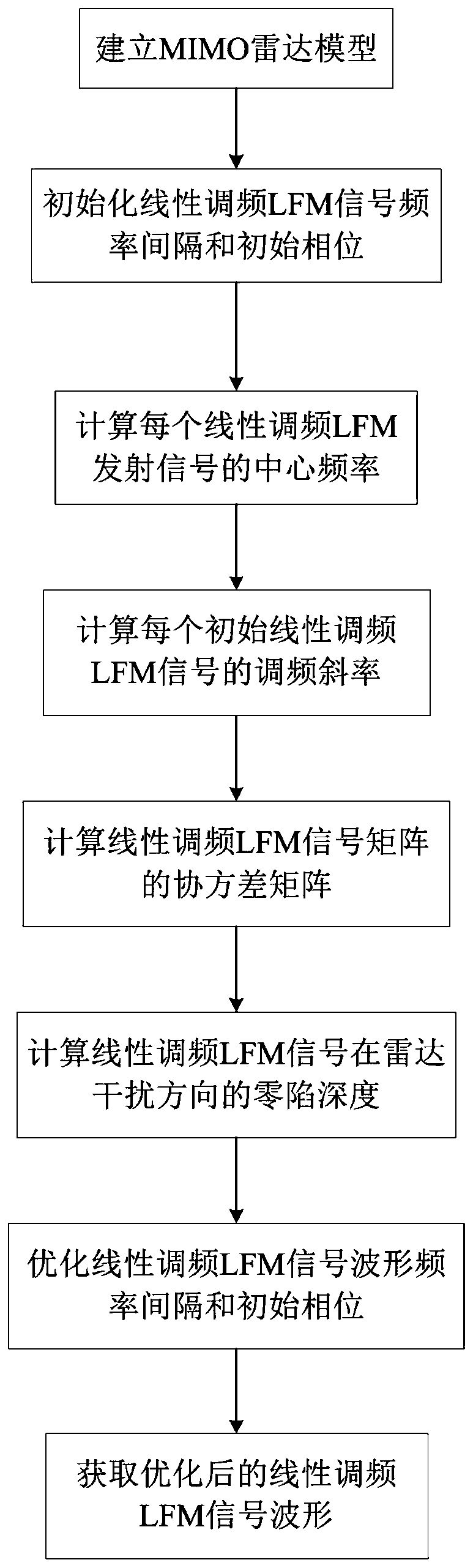
[0036] Reference attached figure 1 , To further describe the specific steps of the present invention.

[0037] Step 1. Establish a multiple input multiple output MIMO radar model.

[0038] Choose a number M from a positive integer greater than 2, and arrange M array elements in a straight line to form a multiple-input multiple-output MIMO radar transmitting array. Each array element transmits a chirp LFM signal. The pulse width of the radar signal is T, the total bandwidth of all transmitted signals is B, and the bandwidth Bs of each signal is the same.

[0039] Step 2. Initialize the frequency interval and initial phase of the chirp LFM signal.

[0040] In the range of [0, T], find the interval value of the chirp LFM signal frequency whose 3dB main lobe of the emission energy pattern is equal to 3dB of the desired pattern main lobe, and use this value as the initial value of the chirp LFM ...


PUM


Abstract

The invention discloses a method for designing a zero-setting waveform of an LFM signal of an MIMO radar. The method comprises: step one, establishing an MIMO radar model; step two, initializing an LFM signal frequency interval and an initial phase; step three, calculating the center frequency of each LFM transmitting signal; step four, calculating a frequency modulation slope of each initial LFMsignal; step five, generating a matrix of the LFM signals; step six, calculating a covariance matrix of the LFM signal matrix; step seven, calculating the zero-falling depth of the LFM signal in the direction of radar interference; step eight, calculating the zero-falling depth of the LFM signal in the direction of radar interference; step nine, optimizing a waveform frequency interval and an initial phase of the LFM signal; and step ten, acquiring the optimized LFM signal waveform. The designed waveform has the advantages of good Doppler tolerance and no radiation power to the interference direction.

Description

Technical field [0001] The present invention belongs to the field of radar technology, and further relates to a method for designing a zero waveform for a multiple input multiple output MIMO (Multiple input multiple output) radar linear frequency modulation (LFM) signal in the technical field of radar signal waveform generation. The invention can be used to design a zero-setting waveform of a multiple-input and multiple-output MIMO radar chirp LFM signal that does not radiate power to the interference direction, and the waveform can transmit and zero interference. Background technique [0002] The input multiple output MIMO radar can adjust the transmission waveform according to the specific working mode, so as to allocate the transmission energy reasonably, and has greater flexibility. According to the different working modes, the transmitted waveform can be divided into quadrature waveform, partial correlation waveform and zero-setting waveform. According to the different sign...

Claims


Application Information

Patent Timeline
Patent Type & Authority Applications(China)
IPC IPC(8): G01S7/282
Inventor 赵永波谢煜晨刘宏伟何学辉水鹏朗
Owner XIDIAN UNIV
Why Eureka
Try Eureka