Design method of mimo radar waveform

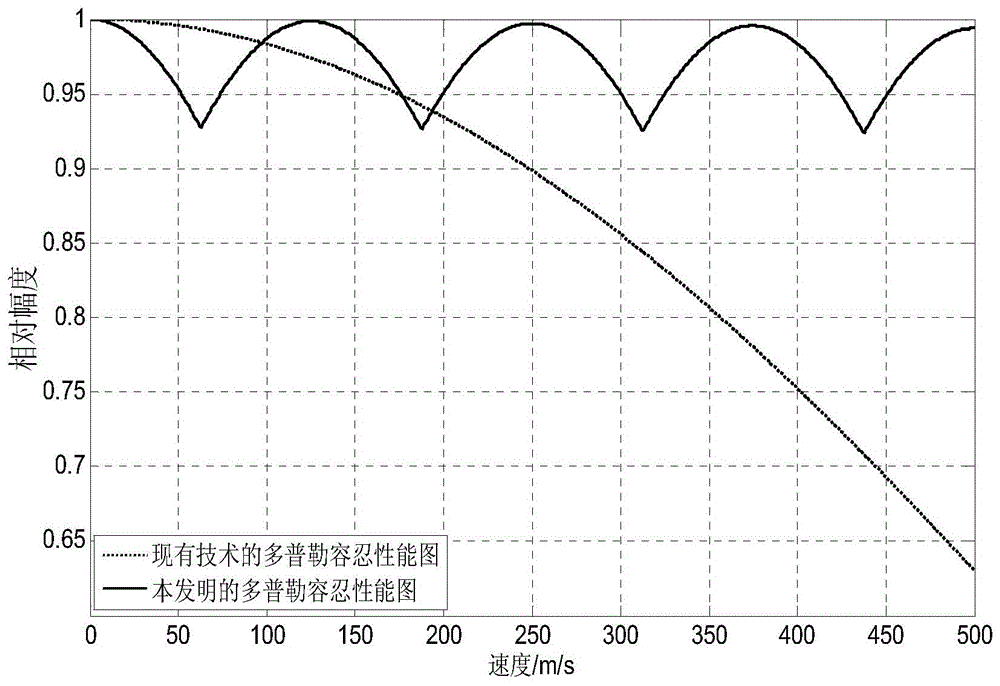
A design method and radar waveform technology, applied in the field of radar, can solve the problems of poor Doppler tolerance, low peak sidelobe level of emission energy function, high computational complexity, etc., to reduce the degree of mismatch in pulse comprehensive processing, reduce Calculation amount, effect of good Doppler tolerance

Active Publication Date: 2015-10-28
XIDIAN UNIV
View PDF3 Cites 2 Cited by
  • Summary
  • Abstract
  • Description
  • Claims
  • Application Information

AI Technical Summary

Problems solved by technology

This method has a lower peak sidelobe level of the transmitted energy function, but also has the problem of high computational complexity
[0005] The above two methods have poor Doppler tolerance due to the use of phase encoding, especially when the target speed is high, the pulse comprehensive processing of the target echo signal will be seriously mismatched, and the target cannot be detected

Method used


Image

  • Design method of mimo radar waveform
  • Design method of mimo radar waveform
  • Design method of mimo radar waveform

Examples


Embodiment Construction

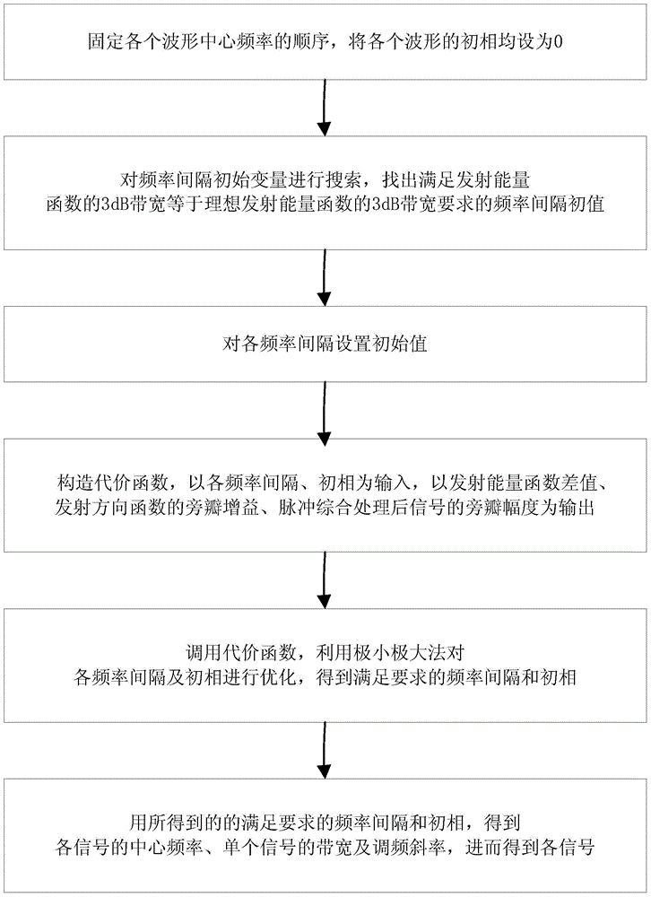
[0040] Refer to figure 1 The specific steps of the present invention are as follows:

[0041] Step 1. Set the parameters.

[0042] Assume that the number of transmitting elements of the MIMO radar antenna is N and the carrier frequency is f 0 , The pulse width of a single waveform is Te, the total bandwidth of N waveforms is B, and the bandwidth Bs of each single waveform is the same; the center frequency f of N waveforms is fixed k The order of f 1 2 N-1 N , And the initial phase of N waveforms All are set to 0, where k=1,2,3,...,N, N≥8.

[0043] Step 2. Obtain the initial frequency interval Δf of the center frequency 0 '.

[0044] 2a) Define the frequency interval of each waveform as Δf m =f m+1 -f m , Let the frequency interval of each waveform Δf m Both are equal to the frequency interval initial variable Δf 0 , Where m=1,2,3,...,N-1;

[0045] 2b) Discrete and uniformly take the value of Q points from 0 to 1 / Te, and arrange them from small to large as [h 1 ′,H 2 ′,…,H n ′,…,H Q ′],...


PUM


Abstract

The invention discloses a method for designing MIMO radar waveforms. The method mainly solves the problem in the prior art that tolerance of Doppler is poor in the process of waveform design. The implementation steps of the method include the first step of fixing a set of waveform center frequency sequences of a radar and setting an initial phase to be zero, the second step of searching a frequency interval initial variable to find out a frequency interval initial value which satisfies the requirement that the 3dB bandwidth of an emitted energy function equals to the 3dB bandwidth of an ideal emitted energy function, the third step of setting a frequency interval according to the frequency interval initial value, the fourth step of inputting the frequency interval and the initial phase and outputting an emitted energy function difference value, emitting direction sidelobe gain and the sidelobe magnitude of signals after pulse synthesis to construct a cost function, the fifth step of calling the cost function and optimizing the cost function through the minimax method to obtain the frequency interval and the initial phase meeting the requirement, and the sixth step of obtaining a set of final signals according to the frequency interval and the initial phase and completing the design of the waveforms. The waveforms designed through the method have the advantages of being good in the tolerance of the Doppler and applicable to target detection.

Description

Technical field [0001] The invention belongs to the technical field of radars and relates to a design method of MIMO radar waveforms, which can be used for target detection. Background technique [0002] Multiple input output MIMO radar is an emerging active detection technology. Its radiating antenna and receiving antenna can be flexibly arranged according to system requirements, and each radiating unit can emit different signal waveforms. Transmission waveforms include quadrature waveforms and cross-correlation waveforms, and cross-correlation waveforms are usually required. MIMO radar can use the waveform diversity capability to flexibly design cross-correlation waveforms so that the energy of electromagnetic waves can be focused on the target or area of ​​interest, thereby effectively using electromagnetic energy and suppressing unnecessary clutter interference. In order to better design the cross-correlation waveforms, the current design process is mainly: first optimize t...

Claims


Application Information

Patent Timeline
Patent Type & Authority Patents(China)
IPC IPC(8): G01S7/42G01S7/282
CPCG01S7/2813G01S7/282G01S7/42G01S13/48
Inventor 赵永波杨金柱刘宏伟水鹏朗朱玉堂李慧
Owner XIDIAN UNIV
Why Eureka
Try Eureka