Control device for a medical appliance

A technology of control devices and medical equipment, applied in medical equipment, hospital equipment, general control systems, etc., to achieve the effect of intuitive operation

Active Publication Date: 2017-05-10
TRUMPF MEDIZIA SYST GMBH CO KG
View PDF6 Cites 0 Cited by
  • Summary
  • Abstract
  • Description
  • Claims
  • Application Information

AI Technical Summary

Problems solved by technology

In addition, the operator must be in the vicinity of these operating elements
Moreover, the surgeon himself cannot operate the device, since the operating elements are usually located outside the sterile field and by touching the operating elements the surgeon will become sterile

Method used


Image

  • Control device for a medical appliance
  • Control device for a medical appliance
  • Control device for a medical appliance

Examples


Embodiment Construction

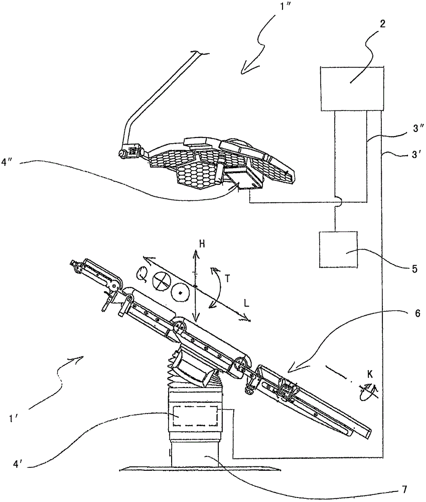
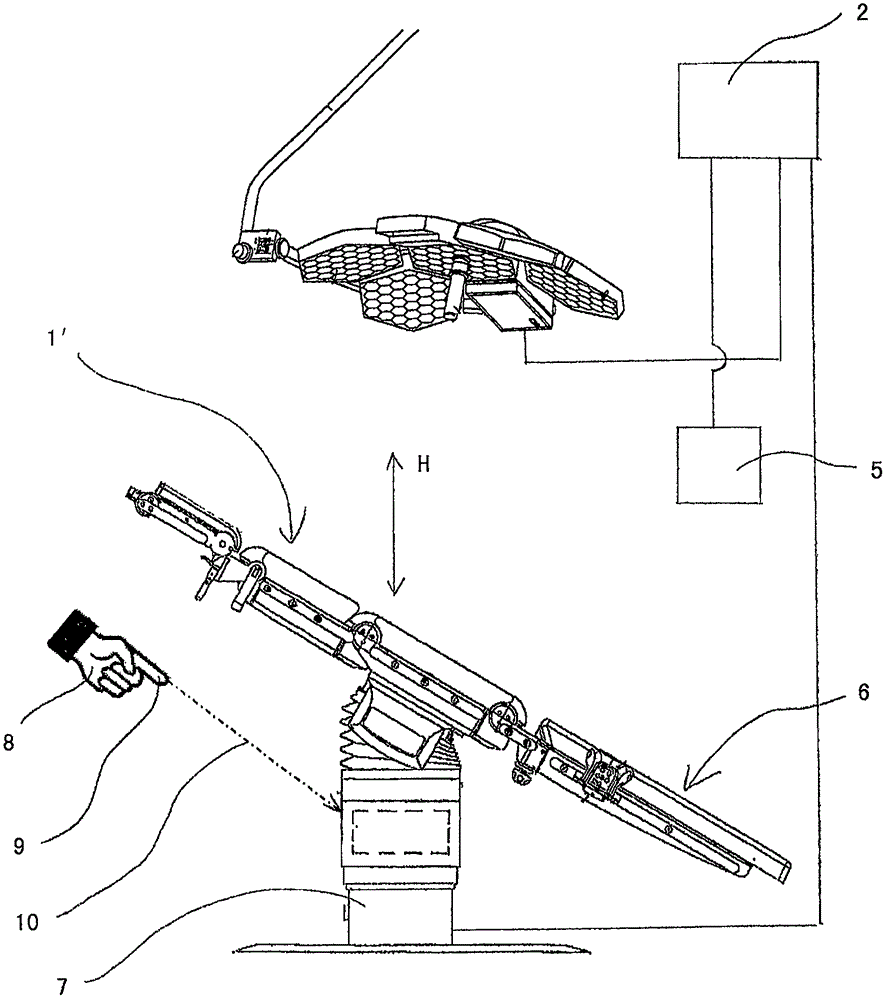
[0013] exist figure 1 In , an operating table 1' and an operating lamp 1" are shown as examples of medical equipment to be controlled. The operating table 1' and the operating lamp 1" are connected to the control device 2 via a data line 3'. In particular, the controller 4 ′ of the operating table 1 ′ and the controller 4 ″ of the operating lamp 1 ″ are connected to the control device 2 via data lines 3 ′, 3 ″. Here, the connection is established via the data lines 3 ′, 3 ″; However, it could alternatively be established wirelessly via radio frequency or infrared. The control device 2 can alternatively also be incorporated in the controller 4' of the operating table 1' or in the controller 4" of the operating light 1", thus essentially in the controller of the medical device.

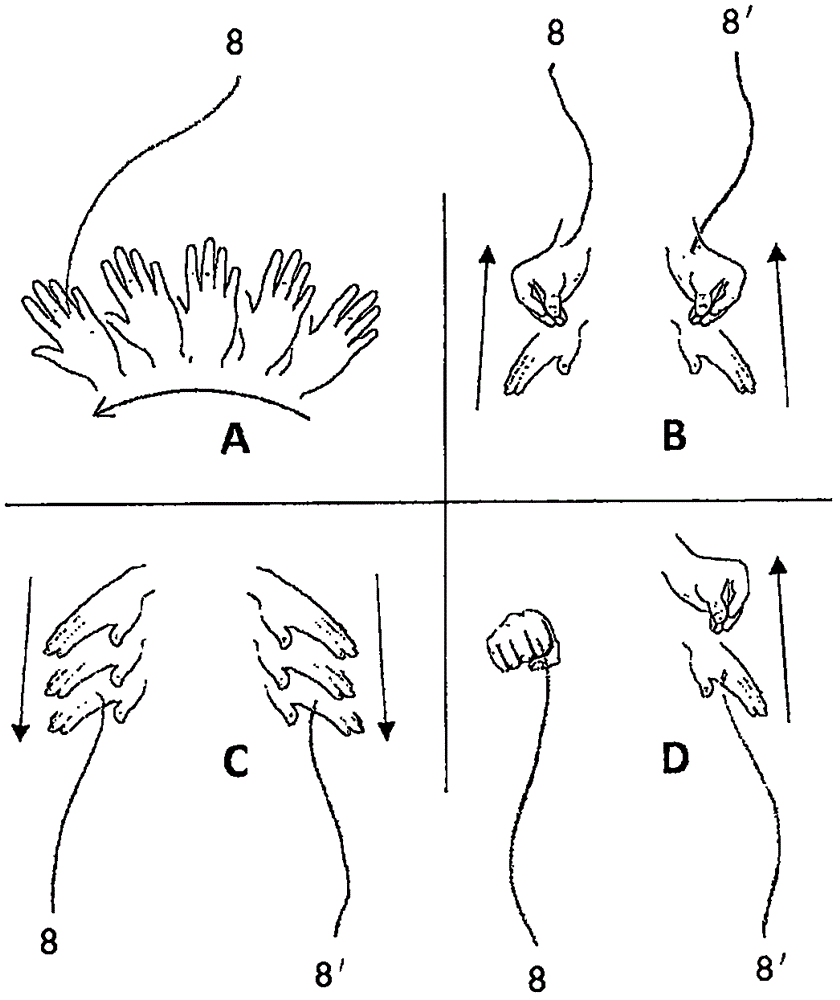
[0014] Furthermore, a 3D sensor 5 is connected to the control device 2 . Through the 3D sensor 5, multiple objects in the room, their shape, position and movement are detected. By detecting motion he...


PUM


Abstract

The invention relates to a control device (2) for a medical appliance, comprising at least one sensor (5) for three-dimensionally detecting an object (8) that is designed to allow, as a result of its orientation, a vector (10) for a direction to be detected, said object (8) being directed towards a target region and the vector (10) forming a point of intersection with a surface of this target region. The control device (2) is adapted to identify in which target region the point of intersection lies, and to initiate an action, predetermined for the target region, using said medical appliance.

Description

technical field [0001] The invention relates to a control device for a medical device, in particular to a control device by means of which a contactless operation of the medical device is possible. Background technique [0002] It is known that medical devices, such as operating tables or operating lights, are operated at the device itself, at a control panel on the wall, or at a remote controller. Furthermore, the operator must be in the vicinity of these operating elements. Moreover, the surgeon himself cannot operate the device, since the operating element is usually located outside the sterile field and by touching the operating element the surgeon would become sterile. [0003] Therefore, an enhanced concerted effort is necessary to operate the device. First, the operator has to be called by a surgeon who has to approach the operating element or find the remote control, check the orientation of the operating element relative to the device, to start or stop, and correc...

Claims


Application Information

Patent Timeline
Patent Type & Authority Applications(China)
IPC IPC(8): G06F19/00A61B6/00A61B6/04A61G7/018A61G13/02
CPCA61B6/467A61B6/548A61G7/018A61G13/02A61B6/4423A61G2203/36A61G2203/12A61G12/004A61B6/0487G06F3/017G08C17/02G08C2201/30G08C2201/32G16H40/63H05B47/125Y02B20/40H05B47/115A61B90/30G05B19/048G05B19/29G05B2219/32287G05B2219/50151
Inventor R·玛尔卡D·格韦拉S·施罗埃德S·厄兹汗A·珀施N·洛夫特菲尔德
Owner TRUMPF MEDIZIA SYST GMBH CO KG
Why Eureka
Try Eureka