LED lamp

A technology of LED lamps and lamp holders, which is applied in the field of lighting, can solve problems such as poor contact, high risk factor, and easy damage, and achieve the effects of preventing loose connections, preventing electric shock accidents, and improving stability

Active Publication Date: 2017-05-17
ZHEJIANG MINGCHUANG OPTO ELECTRONICS TECHNOLOGH
View PDF6 Cites 67 Cited by
  • Summary
  • Abstract
  • Description
  • Claims
  • Application Information

AI Technical Summary

Problems solved by technology

[0002] LED lights can be widely used in various indications, displays, decorations, backlights, general lighting and urban night scenes. LED lights play a very important role in people's daily life. With the development of science and technology, LED lights It has the characteristics of long life, energy saving and high efficiency, and is more and more popular among people. However, most of the LED lighting fixtures in the prior art do not have an electric shock protection structure. Users can easily touch the lamp holder when replacing the lamp holder or maintaining the lamp. contacts in the seat, thus causing electric shock, causing accidents, and causing personal and property losses. At the same time, the existing LED lights are generally connected by screwing power supply. The screwing process is cumbersome and laborious, and the power supply connection is relatively unstable. , It is very easy to cause poor contact and lead to blind lights. Since LED lights are fragile items, they are easily damaged once the voltage is unstable, and the risk factor is high after damage. Emergency treatment devices should be installed to increase the safety during use.

Method used


Image

  • LED lamp
  • LED lamp
  • LED lamp

Examples


Embodiment Construction

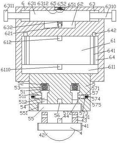
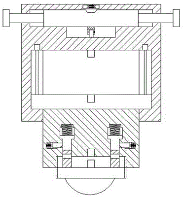
[0023] Such as Figure 1-Figure 8 As shown, an LED lamp of the present invention includes a lamp holder 6 and a lamp cap 4 provided at the bottom of the lamp holder 6. The inner bottom of the lamp holder 6 is provided with a cavity 61, and the left and right sides of the cavity 61 are provided with There is a slide groove 64, a screw rod 641 is arranged in the slide groove 64, the top of the screw rod 641 is connected with the driving machine 642, a slide plate 611 is arranged in the cavity 61, and the two sides of the slide plate 611 The end extends into the sliding groove 64 and is connected with the helical pattern of the screw rod 641. The bottom of the sliding plate 611 is provided with a connecting block 5, and the bottom of the connecting block 5 passes through the bottom wall of the lamp holder 6 and slides to fit. Connection, the inside of the connecting block 5 is provided with a first groove body 51, the top of the first groove body 51 is provided with a counterbore...


PUM


Abstract

The invention discloses an LED lamp. The LED lamp comprises a lamp base and a lamp holder arranged on the bottom of the lamp base. A containing cavity is formed in the bottom in the lamp base. Sliding grooves are formed in the left side and the right side of the containing cavity. Spiral rods are arranged in the sliding grooves, and the tops of the spiral rods are connected with a driver. A sliding plate is arranged in the containing cavity. The two side ends of the sliding plate extend into the sliding grooves and are in cooperation connection with threads of the spiral rods. The bottom of the sliding plate is provided with a connecting block. The bottom of the connecting block penetrates the bottom wall of the lamp base and is in sliding cooperation connection with the bottom wall of the lamp base. First grooves are symmetrically formed in the left and right in the connecting block. Counter bores are formed in the tops of the first grooves. A connecting groove is formed in a bottom end face of the connecting block. Parts, between the connecting groove and the first grooves, of the connecting block are internally provided with through grooves. The outer side wall of each through groove is symmetrically provided with second grooves. First sliding blocks are arranged in the first grooves. First tension springs are arranged between the tops of the first sliding blocks and the corresponding counter bores. The bottom of each first sliding block is provided with a sliding rod extending into the through groove. The LED lamp is simple in structure, convenient to operate, stable in insertion connection and high in safety.

Description

technical field [0001] The invention relates to the technical field of lighting, in particular to an LED lamp. Background technique [0002] LED lights can be widely used in various indications, displays, decorations, backlights, general lighting and urban night scenes. LED lights play a very important role in people's daily life. With the development of science and technology, LED lights It has the characteristics of long life, energy saving and high efficiency, and is more and more popular among people. However, most of the LED lighting fixtures in the prior art do not have an electric shock protection structure. Users can easily touch the lamp holder when replacing the lamp holder or maintaining the lamp. contacts in the seat, thus causing electric shock, causing accidents, and causing personal and property losses. At the same time, the existing LED lights are generally connected by screwing power supply. The screwing process is cumbersome and laborious, and the power sup...

Claims


Application Information

Patent Timeline
Patent Type & Authority Applications(China)
IPC IPC(8): F21K9/20F21V17/10F21V23/06F21Y115/10
CPCF21V17/10F21V23/06
Inventor 方海超
Owner ZHEJIANG MINGCHUANG OPTO ELECTRONICS TECHNOLOGH
Why Eureka
Try Eureka