
Air distribution mechanism for engine, and cam thereof

A valve train, engine technology, applied in engine components, machines/engines, mechanical equipment, etc., can solve the problems of many parts, single function, cumbersome control, etc., to achieve less parts, simple swing arm assembly, easy control Effect

Inactive Publication Date: 2017-05-24
GREAT WALL MOTOR CO LTD
View PDF6 Cites 0 Cited by
  • Summary
  • Abstract
  • Description
  • Claims
  • Application Information

AI Technical Summary

Problems solved by technology

[0002] The valve mechanism of the engine is used to drive the opening and closing of the valve. In order to improve the overall performance of the engine and meet the increasingly stringent emission fuel consumption regulations, it has become a trend to use a variable valve mechanism for the valve mechanism. The variable valve mechanism can be divided into camless Shaft-based variable valve mechanism and camshaft-based variable valve mechanism, but in the related art, the camshaft-based variable valve mechanism has complex structure and single function, such as variable valve lift or variable duration, and many parts , the control is cumbersome

Method used

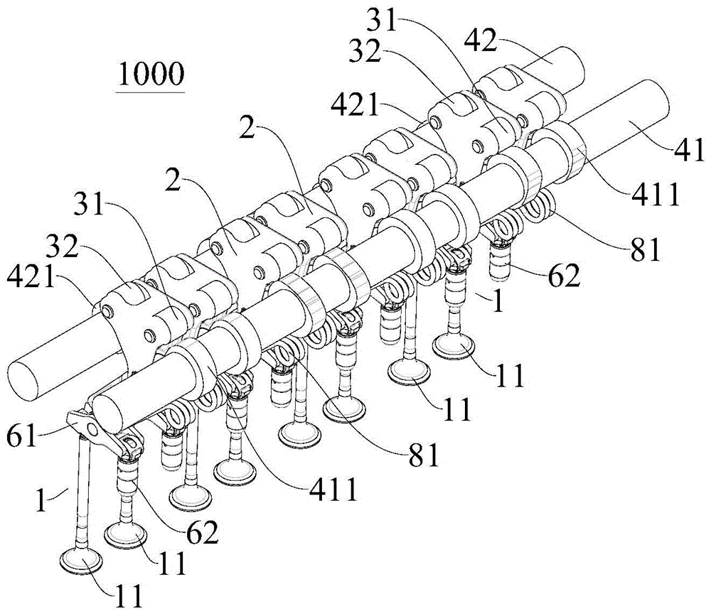
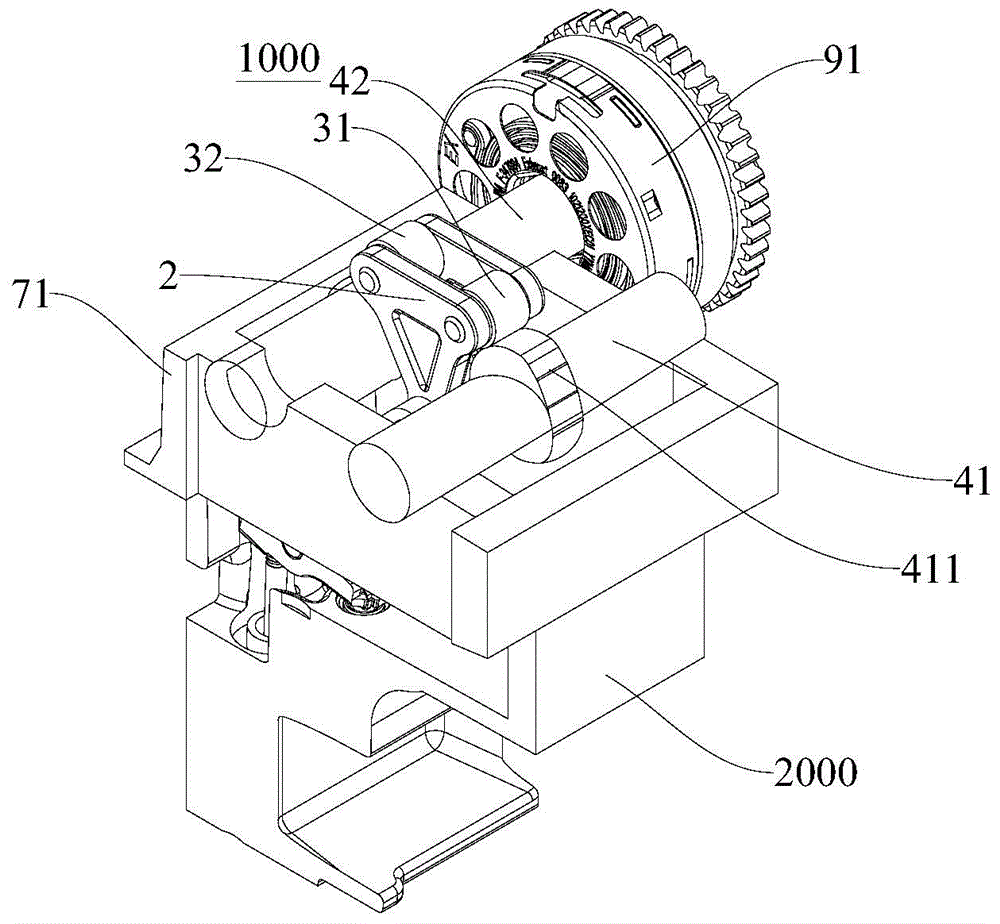
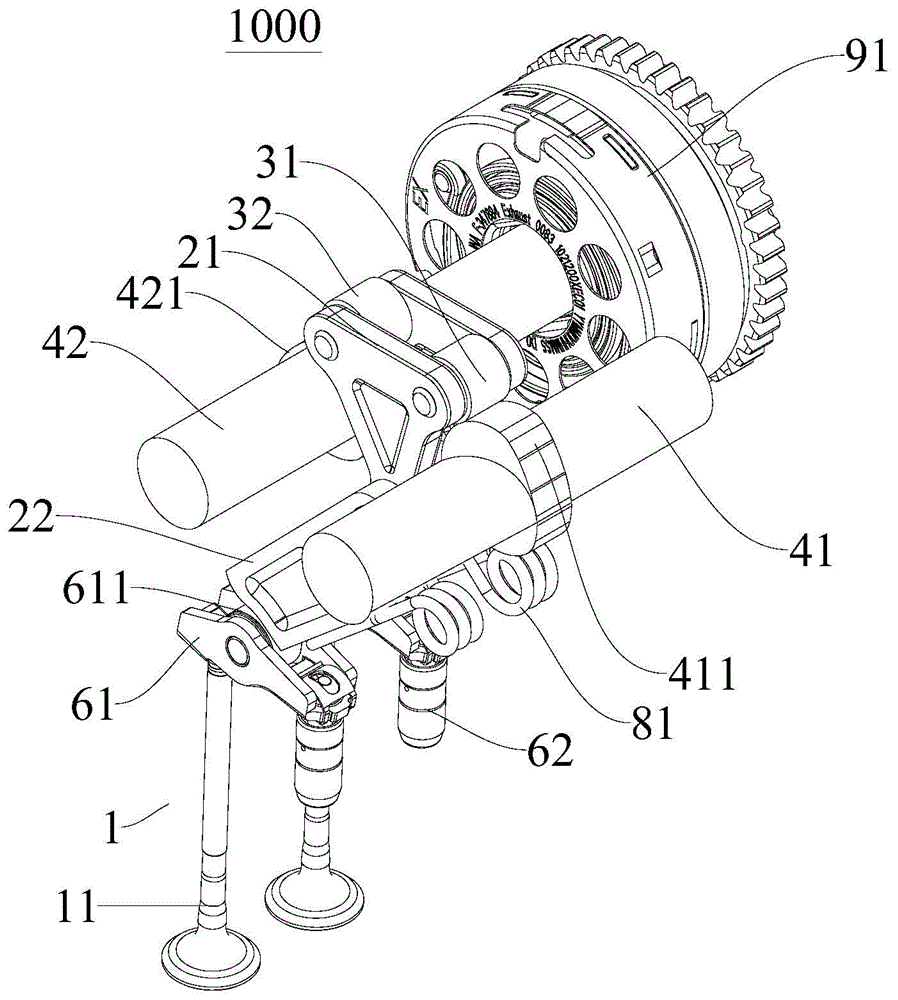

Image

  • Air distribution mechanism for engine, and cam thereof
  • Air distribution mechanism for engine, and cam thereof
  • Air distribution mechanism for engine, and cam thereof

Examples


Embodiment Construction

[0052] It should be noted that, in the case of no conflict, the embodiments of the present invention and the features in the embodiments can be combined with each other.

[0053] The present invention will be described in detail below with reference to the accompanying drawings and examples.

[0054] The body group of the engine is the bracket of the engine, and it is the base body for the assembly of the crank connecting rod mechanism, the gas distribution mechanism and various systems. In this field, generally, the body group is mainly composed of cylinder block, cylinder head, cylinder head gasket and oil pan, etc., the oil pan is generally set at the bottom of the cylinder block, and the cylinder head is set at the top of the cylinder block. A head gasket is provided between the top surface of the cylinder block and the bottom surface of the cylinder head to seal the gap therebetween.

[0055] The cylinder head forms a combustion chamber together with the top of the pisto...


PUM


Abstract

The invention discloses an air distribution mechanism for an engine, and a cam thereof. The air distribution mechanism for the engine comprises an air valve mechanism, a swing arm assembly, a first roller, a second roller, a first camshaft and a second camshaft, wherein each of a first cam profile and a second cam profile comprises a first section, a second section, a third section, a fourth section, a fifth section, a sixth section and a seventh section which are connected end to end, of the corresponding profile; and an air valve is sequentially in a first closed state, an open phase, a closed phase, a second closed state and a third closed state when the first roller is abutted against the first section, the second section, the third section, the fourth section and the fifth section of the first profile respectively and the second roller is correspondingly abutted against the first section, the second section, the third section, the fourth section and the fifth section of the second profile respectively. The air distribution mechanism for the engine further comprises a phase adjustment mechanism used for adjusting the relative phases of the first camshaft and the second camshaft. The air distribution mechanism for the engine, which is disclosed by the embodiment of the invention, is capable of realizing a variable duration period of the air valve.

Description

technical field [0001] The invention relates to the field of automobile construction, in particular to a gas distribution mechanism for an engine and a cam thereof. Background technique [0002] The valve mechanism of the engine is used to drive the opening and closing of the valve. In order to improve the overall performance of the engine and meet the increasingly stringent emission fuel consumption regulations, it has become a trend to use a variable valve mechanism for the valve mechanism. The variable valve mechanism can be divided into camless Shaft-based variable valve mechanism and camshaft-based variable valve mechanism, but in the related art, the camshaft-based variable valve mechanism has complex structure and single function, such as variable valve lift or variable duration, and many parts , the control is cumbersome. Contents of the invention [0003] In view of this, the present invention aims to provide a gas distribution mechanism for an engine, which has ...

Claims


Application Information

Patent Timeline
Patent Type & Authority Applications(China)
IPC IPC(8): F01L1/04F01L1/08F01L1/06F01L1/344
Inventor 程超刘占强桂小林
Owner GREAT WALL MOTOR CO LTD
Learn More