Turbine rotor grinding fixture

A turbine rotor and grinder technology, which is used in the manufacture of tools, grinding workpiece supports, grinders, etc., can solve the problems of rotor blades and blades that cannot be ground.

Active Publication Date: 2018-11-27
CHINA HANGFA SOUTH IND CO LTD
View PDF5 Cites 1 Cited by
  • Summary
  • Abstract
  • Description
  • Claims
  • Application Information

AI Technical Summary

Problems solved by technology

[0005] The invention provides a turbine rotor grinding fixture to solve the technical problem that some blades cannot be ground because the rotor blades cannot be thrown to the maximum diameter when the turbine rotor is ground on an ordinary machine tool

Method used


Image

  • Turbine rotor grinding fixture
  • Turbine rotor grinding fixture
  • Turbine rotor grinding fixture

Examples


Embodiment Construction

[0033] It should be noted that, in the case of no conflict, the embodiments in the present application and the features in the embodiments can be combined with each other. The present invention will be described in detail below with reference to the accompanying drawings and examples.

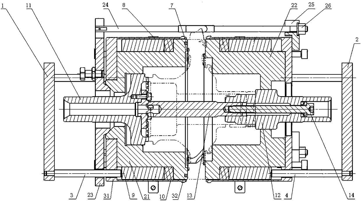
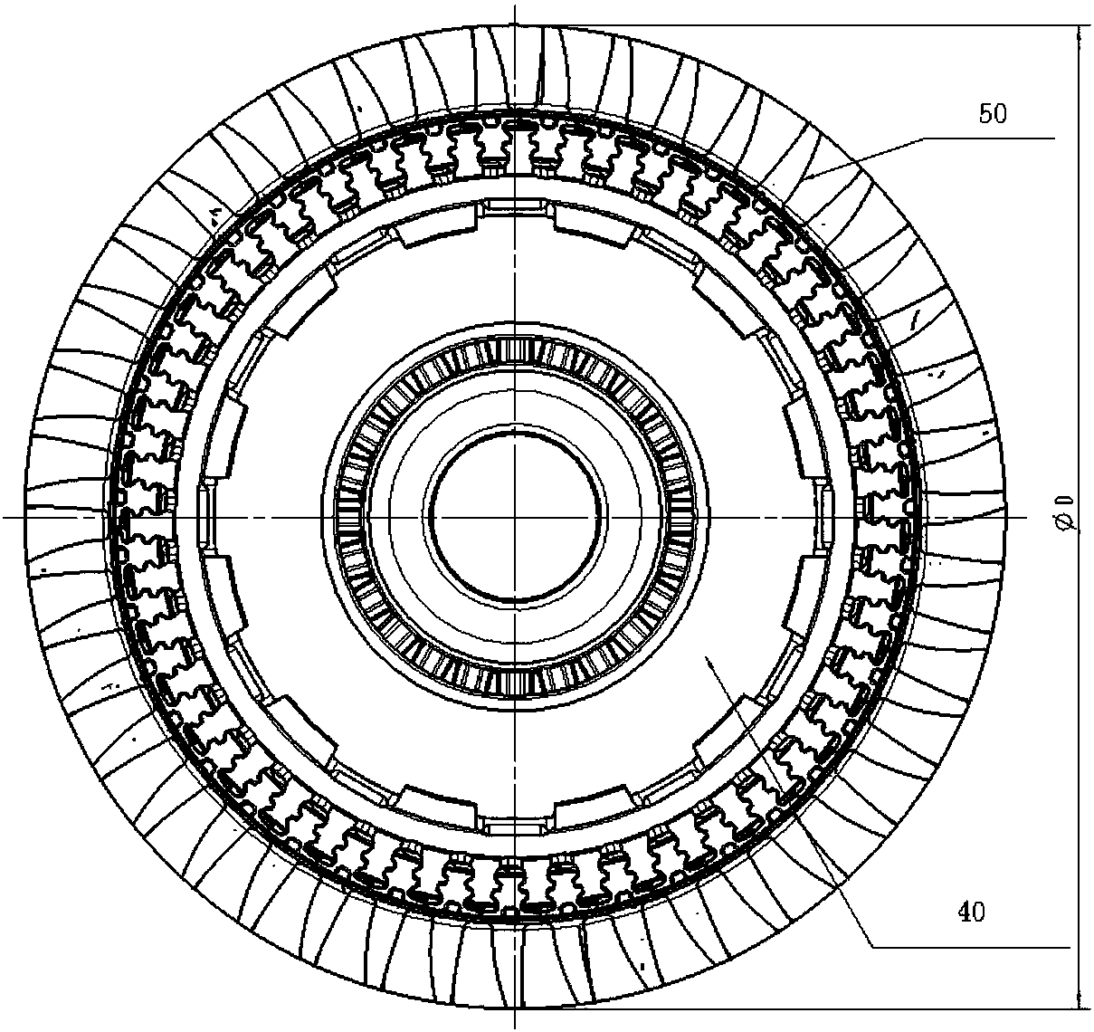
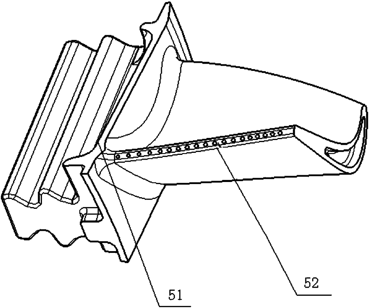
[0034] refer to figure 1 , figure 2 and image 3 , the preferred embodiment of the present invention provides a turbine rotor grinding jig, used to spread the turbine rotor blades, the grinding jig includes a support assembly for fixing the turbine disk 40, which is clearance fit with the support assembly and used for pressing The positioning assembly tightens the two end surfaces of the turbine rotor, the tensioning assembly located on both sides of the turbine disk 40 abuts against the positioning assembly and is used to stretch the turbine rotor blade 50 to the maximum diameter, and is used to apply pressure for the tensioning assembly to brace A press that drives the turbine rotor blade...


PUM


Abstract

The invention discloses a turbine rotor grinder clamp. The turbine rotor grinder clamp is used for propping blades of a turbine rotor open. The turbine rotor grinder clamp comprises a support assembly, a locating assembly, tightly propping assemblies and a press machine, wherein the support assembly is used for fixing a turbine disk, the locating assembly is in clearance fit with the support assembly and used for tightly pressing the two end faces of the turbine rotor, the tightly propping assemblies are located on the two sides of the turbine disk, abut against the locating assembly and are used for propping the blades of the turbine rotor to the maximum diameter, and the press machine is used for applying press force so as to enable the tightly propping assemblies to prop the blades of the turbine rotor open. The support assembly and the locating assembly fix the turbine disk and tightly press the end faces of the turbine rotor, and the press machine applies the press force to the tightly propping assemblies so as to enable the tightly propping assemblies to prop the blades of the turbine rotor open to the maximum diameter. The turbine rotor grinder clamp effectively solves the technical problem that when the turbine rotor is ground on an ordinary machine tool, because the blades of the rotor cannot be opened to the maximum diameter, some blades cannot be ground.

Description

technical field [0001] The invention relates to the field of engine assembly, in particular to a grinding fixture for a turbine rotor. Background technique [0002] Before the engine gas turbine rotor is assembled to the engine, the entire blade tip needs to be ground. The diameter of the grinding is the maximum diameter φD of the blade rotating at high speed in the engine. At present, the end teeth of the engine gas turbine rotor are mainly fixed. On the end teeth of the grinder jig, use the tie rod, pressure plate, washer, and nut to tighten the gas turbine rotor, put the grinder jig with the gas turbine rotor on the grinder, and use the double tip of the grinder to withstand the center holes at both ends of the tie rod. The machine tool starts to rotate, and the tip of the blade is thrown out of the maximum diameter φD by the centrifugal force of the machine tool rotation, and the grinding wheel of the grinder starts to grind the tip of the blade after the grinding diamet...

Claims


Application Information

Patent Timeline
Patent Type & Authority Patents(China)
IPC IPC(8): B24B19/14B24B41/06
CPCB24B19/14B24B41/06
Inventor 高晓龙周红梅谭师师张菊绒郭慧英
Owner CHINA HANGFA SOUTH IND CO LTD
Why Eureka
Try Eureka