an electric device

A technology for power equipment and wires, applied in the field of wire wrapping equipment, can solve problems such as difficulty in meeting different needs, motor damage, and wire wrapping equipment cannot be operated independently, and achieves the effect of stable operation and improved efficiency.

Active Publication Date: 2019-03-08
重庆中启瀚电力工程有限公司
View PDF5 Cites 0 Cited by
  • Summary
  • Abstract
  • Description
  • Claims
  • Application Information

AI Technical Summary

Problems solved by technology

[0002] With the development of society, more and more wires are used. Wires refer to wires that conduct current. In the process of producing wires, it is usually necessary to wrap the wires to facilitate storage and use. Traditional wire wrapping equipment is usually used to improve Surrounding efficiency The rotation shaft of the motor is directly connected in series with the wire winding cylinder, so that the rotation of the motor needs to be stopped before the wire winding cylinder can be replaced after the wire winding is completed. Stopping the motor frequently will easily cause damage to the motor. During the processing, When different amounts of wire wrapping are required, traditional wire wrapping equipment cannot be operated independently, and it is difficult to meet different needs

Method used


Image

  • an electric device
  • an electric device
  • an electric device

Examples


Embodiment Construction

[0020] All the features disclosed in this specification, or all disclosed methods or steps in the process, except for mutually exclusive features and / or steps, can be combined in any manner.

[0021] Any feature disclosed in this specification (including any appended claims, abstract and drawings), unless specifically stated, can be replaced by other equivalent or equivalent alternative features. That is, unless otherwise stated, each feature is just one example of a series of equivalent or similar features.

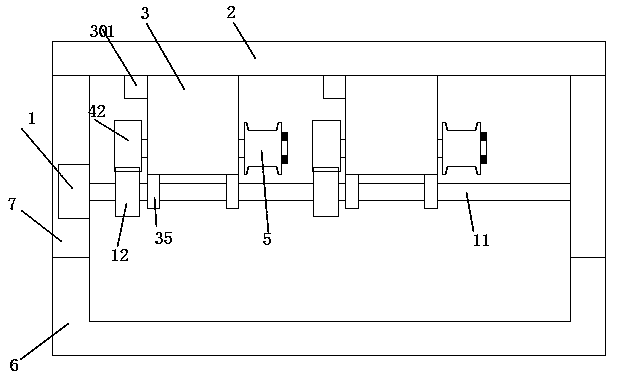
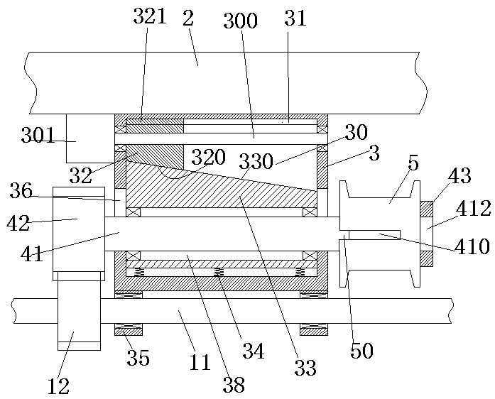
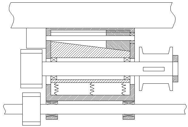
[0022] Such as Figure 1-4 As shown, a power device of the present invention includes a first electric motor 1, a first rotating shaft 11 connected to the first electric motor 1, a fixed plate 2, and multiple sets of wire surrounding mechanisms fixedly installed at the lower end of the fixed plate The first electric motor 1 is fixedly installed in the mounting plate 7, and the lower end of the mounting plate 7 is fixedly provided with a tripod 6, and the front and rear ends ...


PUM


Abstract

The invention relates to power equipment which comprises a first motor, a first rotary shaft connected to the first motor, a fixed plate and multiple groups of electric wire coiling mechanisms fixedly mounted at the lower end of the fixed plate; the first motor is fixedly mounted in a mounting plate, a foot stool is fixedly arranged at the lower end of the mounting plate, the front and back end surfaces of the foot stool are obliquely arranged, and multiple groups of positioning gear-shaped wheels are fixedly arranged on the first rotary shaft; each of the electric wire coiling mechanisms comprises a housing which is fixedly mounted at the lower end of the fixed plate, wherein a sliding chamber is arranged in the housing, a sliding block which can slide up and down is mounted in the sliding chamber, a setting tank communicated in left and right is formed in the sliding block, a rotary shaft is rotatably mounted in the setting tank through a bearing, a movable gear-shaped wheel engaged with the positioning gear-shaped wheel is fixedly mounted at the left end of the rotary shaft, and an electric wire coiling barrel is mounted at the right end of the rotary shaft by matching a bump with a bump groove.

Description

Technical field [0001] The present invention relates to the field of power equipment, in particular to a wire surrounding equipment. Background technique [0002] With the development of society, more and more wires are used. Wires refer to wires that conduct current. In the process of producing wires, it is usually necessary to surround the wires to facilitate storage and use. Traditional wire wrapping equipment is usually to improve The winding efficiency connects the rotating shaft of the motor directly to the wire winding drum in series, so that after the wire winding is completed, the rotation of the motor needs to be stopped before the wire winding drum can be replaced. Often stopping the motor can easily cause damage to the motor. In the process of processing, When the amount of wire wrapping is required to be different, the traditional wire wrapping equipment cannot be operated independently, and it is difficult to meet different needs. Summary of the invention [0003] T...

Claims


Application Information

Patent Timeline
Patent Type & Authority Patents(China)
IPC IPC(8): B65H67/04B65H54/70
CPCB65H54/70B65H67/0405B65H2701/33
Inventor 俞群涛
Owner 重庆中启瀚电力工程有限公司
Why Eureka
Try Eureka