Winding equipment for textile silk threads

A winding and equipment technology, which is applied in the field of textile silk winding equipment, can solve the problems of easy failure, lower production efficiency, and operator injury, etc., and achieve the effect of stable operation, increased stability, and improved winding efficiency

Inactive Publication Date: 2017-07-07
惠安县蓝普欣日用品有限公司
View PDF5 Cites 0 Cited by
  • Summary
  • Abstract
  • Description
  • Claims
  • Application Information

AI Technical Summary

Problems solved by technology

[0003] The winding of the silk thread requires the rotating shaft to drive the winding barrel to rotate continuously. In order to improve efficiency, the winding barrel generally rotates at high speed. The traditional silk winding machine needs to stop the main shaft motor after the winding of the silk thread is completed. For the replacement of the winding drum, if the spindle motor is frequently shut down and started, it is prone to failure, which greatly affects the service life of the spindle motor, and in the process of replacing the winding drum, the spindle motor is accidentally turned on, which will cause injury to the operator and is easy Therefore, there are certain safety hazards in the traditional silk winding machine. In production, sometimes it is necessary to wind bobbins with different wire volumes to meet different needs. The traditional silk winding machine needs to deal with these different winding The spools of the amount of thread are operated separately, thus greatly reducing the production efficiency

Method used


Image

  • Winding equipment for textile silk threads
  • Winding equipment for textile silk threads
  • Winding equipment for textile silk threads

Examples


Embodiment Construction

[0021] All features disclosed in this specification, or steps in all methods or processes disclosed, may be combined in any manner, except for mutually exclusive features and / or steps.

[0022] Any feature disclosed in this specification (including any appended claims, abstract and drawings), unless expressly stated otherwise, may be replaced by alternative features which are equivalent or serve a similar purpose. That is, unless expressly stated otherwise, each feature is one example only of a series of equivalent or similar features.

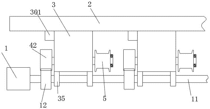
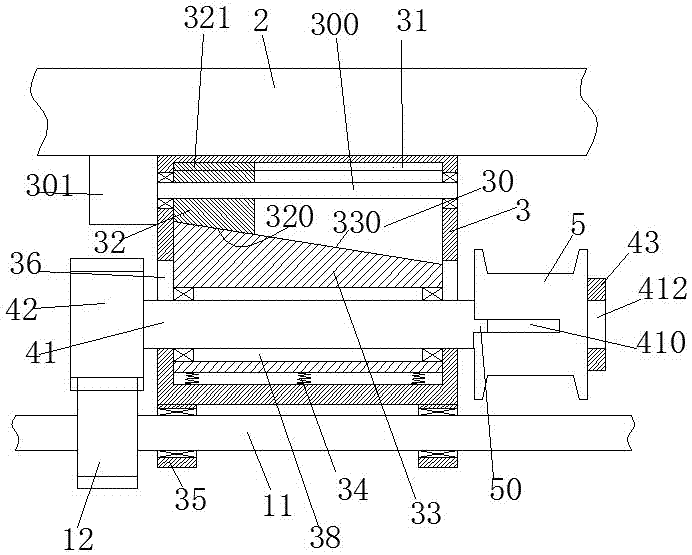
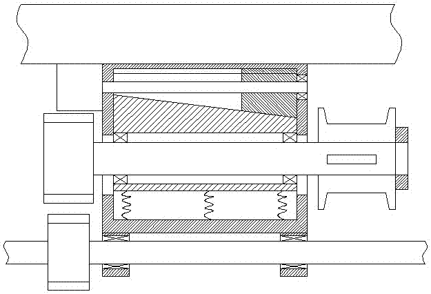
[0023] Such as Figure 1-4 As shown, a winding device for textile thread of the present invention includes a motor-1, a rotating shaft 11 dynamically connected to the motor-1, a fixed frame 2, and a plurality of coils fixedly installed at the lower end of the fixed frame 2. The winding assembly includes a plurality of fixed gears 12 fixedly arranged on the rotating shaft 11, the winding assembly includes an installation housing 3 fixedly inst...


PUM


Abstract

A kind of winding equipment of textile thread, comprising motor 1, a rotating shaft power-connected with motor 1, a fixing frame and a plurality of winding components fixedly installed at the lower end of the fixing frame, and a plurality of winding components fixedly arranged on the rotating shaft The gear is fixed, the winding assembly includes a housing fixedly installed at the lower end of the fixing frame, a sliding cavity is arranged in the mounting housing, a sliding block is installed in the sliding cavity to slide up and down, and a sliding block is set in the sliding block There is a left and right through installation groove, in which a straight shaft is rotatably installed through a bearing, and a moving gear capable of meshing with the fixed gear is fixedly installed on the left end of the straight shaft, and the right end of the straight shaft The winding cylinder is installed through the cooperation of the bar key and the bar key groove. The top wall of the sliding chamber is provided with guide grooves extending left and right, and the upper ends of the left and right side walls of the installation housing are rotatably installed with moving threaded rods. A moving extruding block is mounted on the moving threaded rod in screw fit.

Description

technical field [0001] The invention relates to the field of textile supporting equipment, in particular to a winding equipment for textile threads. Background technique [0002] In the textile field, multiple processes are required to complete a product, and almost every process uses different textile equipment, among which winding equipment is one of the indispensable textile equipment. After the twisting machine produces the silk thread, a winding machine is needed to wind the thread on the bobbin, so as to facilitate handling and subsequent production processes, such as spinning machinery. [0003] The winding of the wire needs the rotating shaft to drive the winding drum to rotate continuously. In order to improve the efficiency, the winding drum is generally rotated at high speed. The traditional wire winding machine needs to stop the main shaft motor after the wire winding is completed. For the replacement of the winding drum, if the spindle motor is frequently stopp...

Claims


Application Information

Patent Timeline
IPC IPC(8): B65H67/04B65H54/20B65H54/74
CPCB65H67/0411B65H54/20B65H54/74B65H67/0417B65H2403/55B65H2701/31
Inventor 范盛林
Owner 惠安县蓝普欣日用品有限公司
Why Eureka
Try Eureka