
Block stator, manufacturing method of block stator, motor with block stator and household appliance

A manufacturing method and stator technology, applied in the manufacture of motor generators, electrical components, electromechanical devices, etc., can solve the problems of low winding efficiency, low first pass rate of motors, and large copper consumption, so as to improve winding efficiency and production Efficiency, fewer wiring and tap methods, convenient and practical performance

Inactive Publication Date: 2014-08-06
GD MIDEA ENVIRONMENT APPLIANCES MFG +1
View PDF15 Cites 14 Cited by
  • Summary
  • Abstract
  • Description
  • Claims
  • Application Information

AI Technical Summary

Problems solved by technology

This traditional structure has problems such as low efficiency, complicated process, many working hours, many materials used, low yield, poor quality, and difficulty in reducing costs. The reasons are as follows:
[0003] (1) The length-to-diameter ratio of single-phase squirrel-cage motors is usually not large. When distributed windings are used, the ends are very long, the utilization rate of copper is low, the copper consumption is large, and the efficiency is low;
[0004] (2) The distributed winding process is complicated, the winding efficiency is low, and the labor cost is high;
[0005] (3) The ends of the distributed windings overlap, which is easy to cause damage during assembly, and the first pass rate of the motor is low and the quality is not high;
[0006] (4) The integral stamping of the stator sheet produces a large amount of leftover material, and the utilization factor of the silicon steel sheet is low
However, if the stator block technology is used, the number of thread ends will increase, and it is easy to break the wire when the block stator is combined, making it difficult to manufacture.

Method used


Image

  • Block stator, manufacturing method of block stator, motor with block stator and household appliance
  • Block stator, manufacturing method of block stator, motor with block stator and household appliance
  • Block stator, manufacturing method of block stator, motor with block stator and household appliance

Examples


Embodiment Construction

[0071] Embodiments of the present invention are described in detail below, examples of which are shown in the drawings, wherein the same or similar reference numerals designate the same or similar elements or elements having the same or similar functions throughout. The embodiments described below by referring to the figures are exemplary only for explaining the present invention and should not be construed as limiting the present invention.

[0072] In describing the present invention, it should be understood that the terms "center", "longitudinal", "transverse", "upper", "lower", "front", "rear", "left", "right", " The orientations or positional relationships indicated by "vertical", "horizontal", "top", "bottom", "inner" and "outer" are based on the orientations or positional relationships shown in the drawings, and are only for the convenience of describing the present invention and Simplified descriptions, rather than indicating or implying that the device or element refe...


PUM


Abstract

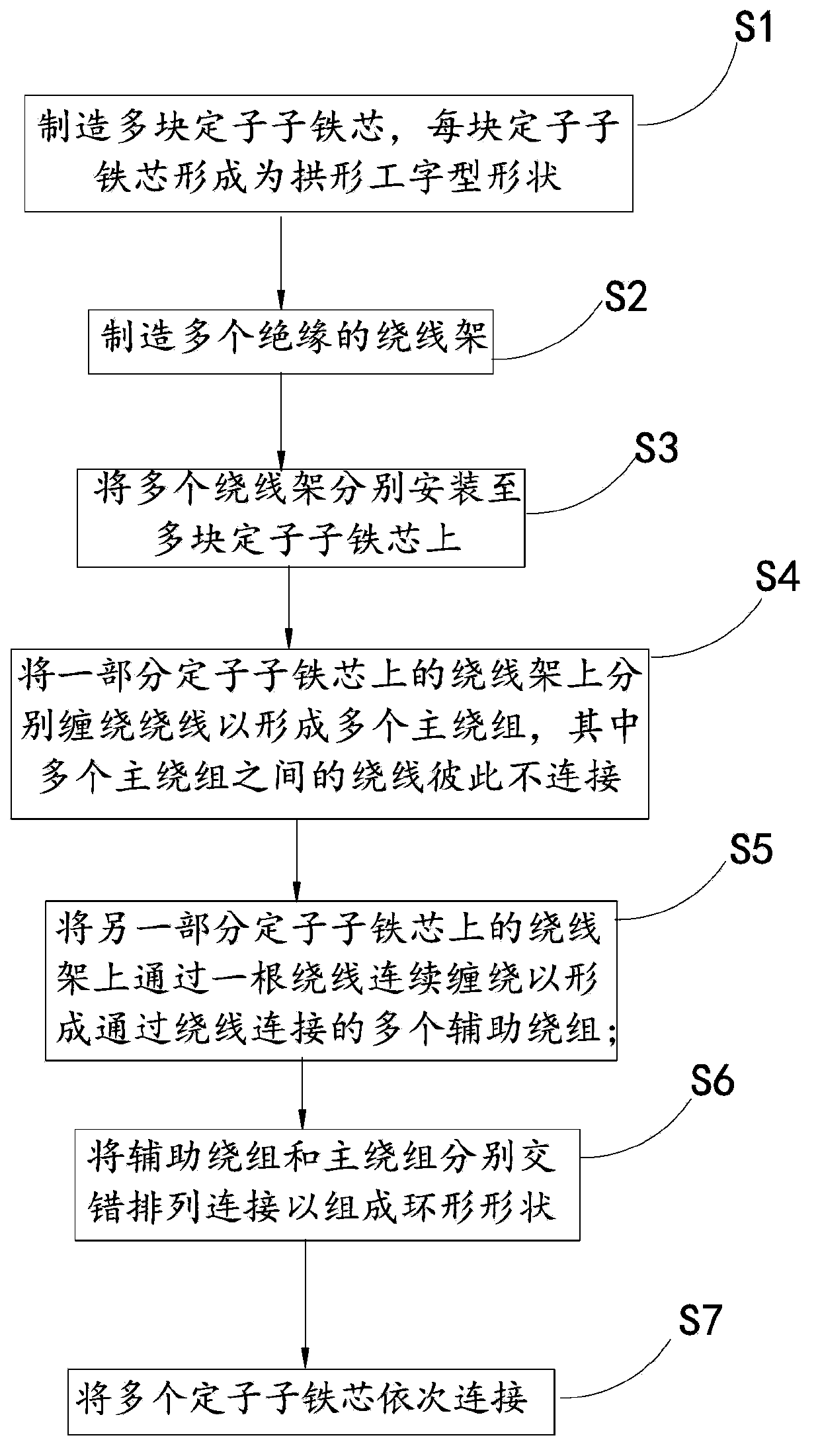
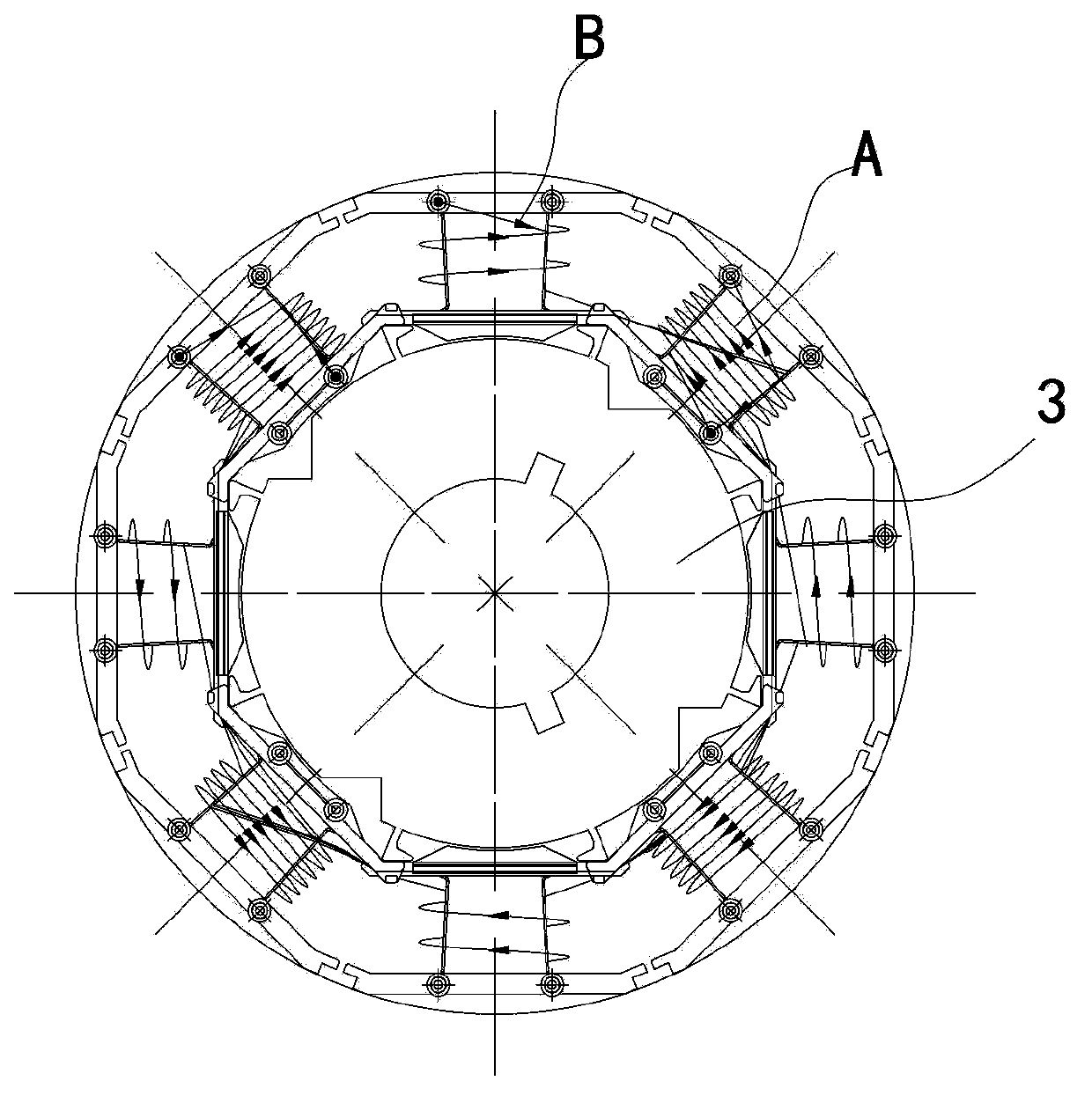
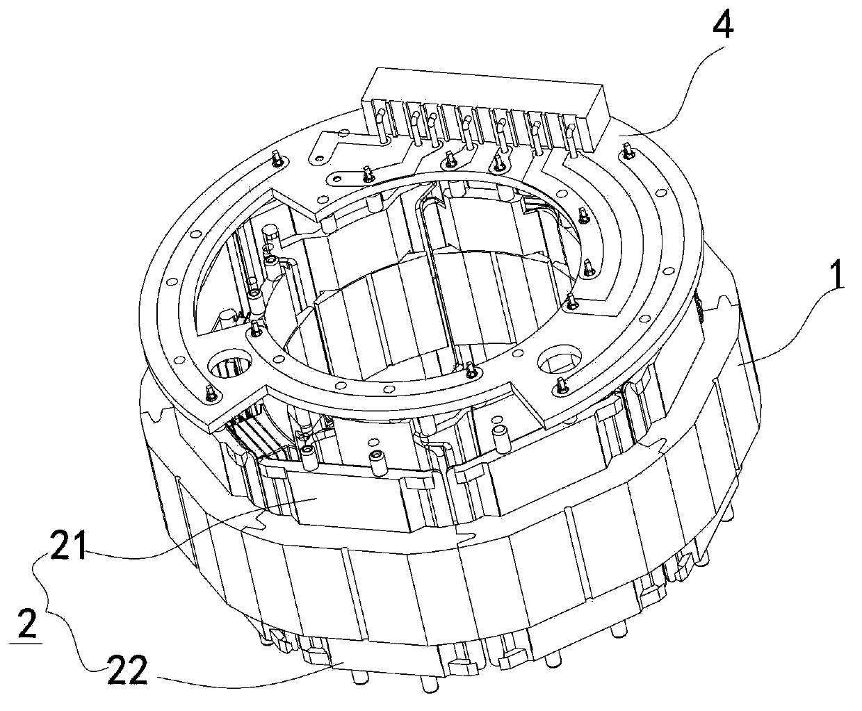
A segment stator and manufacturing method thereof, an electric machine and a household electrical appliance with same. The manufacturing method comprises the following steps: manufacturing a plurality of stator segment cores (1); manufacturing a plurality of insulated winding frames (2); installing the plurality of winding frames (2) onto the plurality of stator segment cores (1), respectively; winding main coils (5a) around the winding frames (2) on some of the stator segment cores (1) to form a plurality of main windings (A), wherein the main coils (5a) of the plurality of main windings (A) are not connected to each other; winding continuously a secondary coil (5b) around the winding frames (2) on the other stator segment cores (1) to form a plurality of secondary windings (B) connected by the secondary coil; arranging and connecting the secondary windings (B) and the main windings (A) alternately to form a ring shape; and connecting the plurality of stator segment cores (1) in turn. The manufacturing method has a high winding speed.

Description

technical field [0001] The invention relates to the field of motors used in household appliances, and in particular to a segmented stator of the motor and a manufacturing method thereof, a motor with the segmented stator, and a household appliance with the motor. Background technique [0002] Single-phase squirrel-cage asynchronous motors are the most widely used motors in household appliances. Traditionally, the stator winding of this kind of motor is composed of two sets of short-distance distributed windings, the main and the auxiliary, and the stator and rotor cores are formed by stacking integral punched sheets. This traditional structure has problems such as low efficiency, complicated process, many working hours, many materials used, low yield, poor quality, and difficulty in reducing costs. The reasons are as follows: [0003] (1) The length-to-diameter ratio of single-phase squirrel-cage motors is usually not large. When distributed windings are used, the ends are ...

Claims


Application Information

Patent Timeline
Patent Type & Authority Applications(China)
IPC IPC(8): H02K15/095H02K1/14
CPCH02K1/148H02K2203/09H02K3/522
Inventor 彭颖卿李剑雄廖启国汪志刚
Owner GD MIDEA ENVIRONMENT APPLIANCES MFG
Learn More