An Improved Textile Roller

An improved roller technology, which is applied in textiles and papermaking, spinning machines, drafting equipment, etc., can solve the problems of complex operation, no mention of the problem of rollers, and the inability to automatically polymerize and press the yarn, so as to achieve convenient combined operation , High stability effect

Active Publication Date: 2021-06-18
杭州诚天旺丝绸有限公司
View PDF17 Cites 0 Cited by
  • Summary
  • Abstract
  • Description
  • Claims
  • Application Information

AI Technical Summary

Problems solved by technology

[0003] However, the existing rollers have the following problems in the use process. a. When assembling the traditional rollers and the supporting bearings, it is necessary to manually use tools to fix the bearings and rollers and install them on the frame for use. The operation is complicated, and the installation of the rollers The disassembly operation is complicated, which reduces the efficiency of daily maintenance of rollers. b. In textile operations, rollers of different specifications and diameters need to be prepared according to textile requirements of different specifications. Traditional roller diameter specifications cannot be adjusted, and the diameter cannot be adapted according to work requirements. changes, and the traditional rollers cannot polymerize the yarns in operation, and the loose yarns cannot be automatically polymerized and pressed when they pass through the rollers, and auxiliary equipment is needed to polymerize the yarns, which increases the cost of spinning operations
[0004] For the technical problems existing in the use of textile rollers at present, personnel in related technical fields have made appropriate improvements after investigations, such as a Chinese invention patent of a textile roller with a patent number of 2013103161180, which can increase the tension on the surface of the roller. Guarantee that there will be no burrs on the surface of the roller, but there is no mention of the problems in the use of the roller mentioned above

Method used


Image

  • An Improved Textile Roller
  • An Improved Textile Roller
  • An Improved Textile Roller

Examples


Embodiment Construction

[0025] The embodiments of the present invention will be described in detail below with reference to the accompanying drawings, but the present invention can be implemented in many different ways defined and covered by the claims.

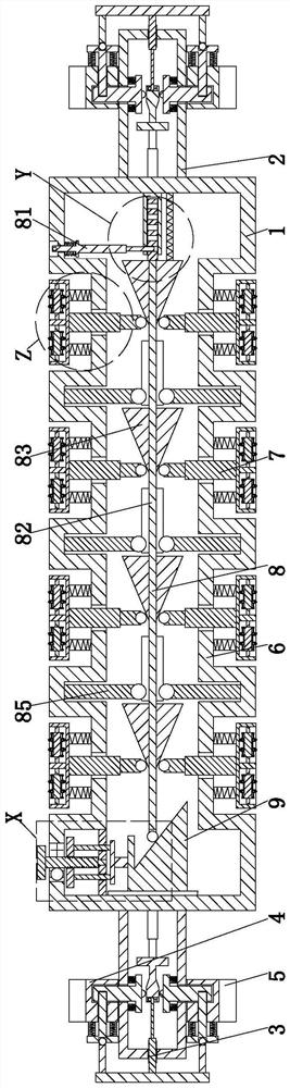
[0026] Such as Figure 1 to Figure 5 As shown, an improved textile roller includes a roller body 1, the left and right ends of the roller body 1 are symmetrically equipped with hollow columns 2, and the hollow column 2 is connected with a fixed ring 4 through a fixing mechanism 3, and the fixed ring 4 is covered A bearing ring 5 is provided, and the roller body 1 has a hollow structure. The roller body 1 is uniformly provided with inner grooves 6 from left to right; The pressing mechanism 8 and the adjusting mechanism 7 lean against the squeezing mechanism 8 , the left end of the roller body 1 is provided with a driving mechanism 9 , and the left end of the squeezing mechanism 8 leans against the driving mechanism 9 .

[0027] Described fixing mech...


PUM


Abstract

The invention relates to an improved textile roller, which includes a roller body, hollow columns are symmetrically installed at the left and right ends of the roller body, a fixed ring is connected to the hollow column through a fixing mechanism, and a bearing ring is sleeved on the fixed ring. It is a hollow structure, and the roller body is uniformly provided with inner grooves from left to right. The present invention can solve the following difficult problems existing in the use of the existing rollers. a. When assembling the traditional rollers and the supporting bearings, manual tools are required to fix the bearings and rollers and install them on the frame for use, which is complicated to operate, and The installation and disassembly of the roller is complicated, which reduces the efficiency of the daily maintenance of the roller. b. In the textile operation, rollers of different specifications and diameters need to be prepared according to the textile requirements of different specifications, and the diameter specifications of the traditional rollers cannot be adjusted.

Description

technical field [0001] The invention relates to the technical field of injection molding, in particular to an improved textile roller. Background technique [0002] Roller is a cylindrical rotating part that plays the role of feeding, drafting, output, etc. in textile machinery. It is widely used in drafting, carding, conveying and other mechanisms. The roller usually mentioned refers to the drafting bottom roller. It is a steel slender shaft with grooves, knurling, or smooth surface on the outer circle. The roller is used in textile machinery. The important components of the roller play a vital role in the quality of the yarn, and the roller needs regular maintenance during use. [0003] However, the existing rollers have the following problems in the use process. a. When assembling the traditional rollers and the supporting bearings, it is necessary to manually use tools to fix the bearings and rollers and install them on the frame for use. The operation is complicated, a...

Claims


Application Information

Patent Timeline
Patent Type & Authority Patents(China)
IPC IPC(8): D01H5/74
CPCD01H5/74
Inventor 童雪松苏林生
Owner 杭州诚天旺丝绸有限公司
Why Eureka
Try Eureka